
Signal detection sensing structure and manufacturing method thereof, and signal detection method

A signal detection and signal technology, applied in measuring devices, measuring ultrasonic/sonic/infrasonic waves, instruments, etc., can solve the problems of difficult signal separation, difficult production, low reliability, etc., to achieve high-precision detection, no heat Discharge effect, simple structure effect

Active Publication Date: 2017-11-07
SHENZHEN INST OF ADVANCED TECH
View PDF6 Cites 10 Cited by
  • Summary
  • Abstract
  • Description
  • Claims
  • Application Information

AI Technical Summary

Problems solved by technology

The preparation process of these two types of sensors is relatively high, and the signal of the piezoelectric material is affected by the temperature. When grasping a hotter or colder object, the temperature change interferes with the detection of the sensory signal.
In addition, an array composed of multiple resistive sensors can also be used to detect sliding signals. There are also photoelectric, acoustic-electric, and electromagnetic sensors that obtain signals indirectly, but they all have complex structures, difficult fabrication, and Disadvantages such as low reliability and difficult to guarantee accuracy
[0005] At present, piezoelectric films such as polyvinylidene can be used to detect contact signals and sliding signals at the same time, but it is difficult to separate the signals, making the detection accuracy of the two signals low

Method used


Image

  • Signal detection sensing structure and manufacturing method thereof, and signal detection method
  • Signal detection sensing structure and manufacturing method thereof, and signal detection method
  • Signal detection sensing structure and manufacturing method thereof, and signal detection method

Examples


Embodiment Construction

[0029] The present invention will be further described in detail below in conjunction with the accompanying drawings and embodiments. It should be understood that the specific embodiments described here are only used to explain the present invention, but not to limit the present invention. In addition, it should be noted that, for the convenience of description, only some structures related to the present invention are shown in the drawings but not all structures.

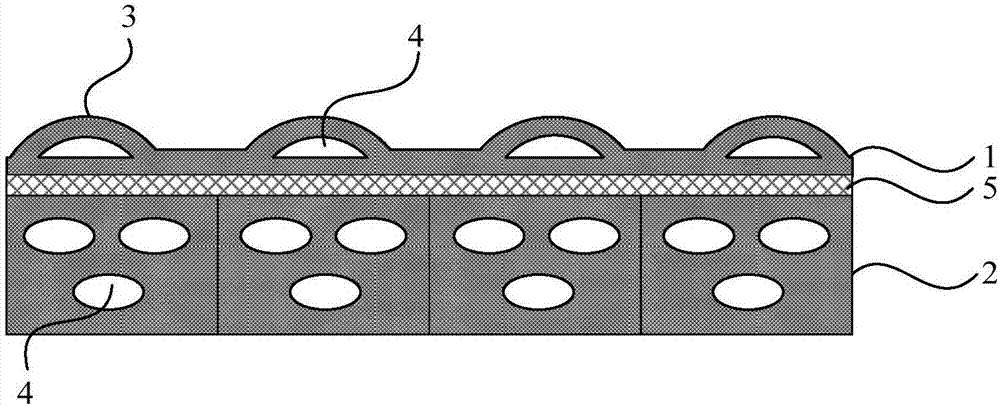
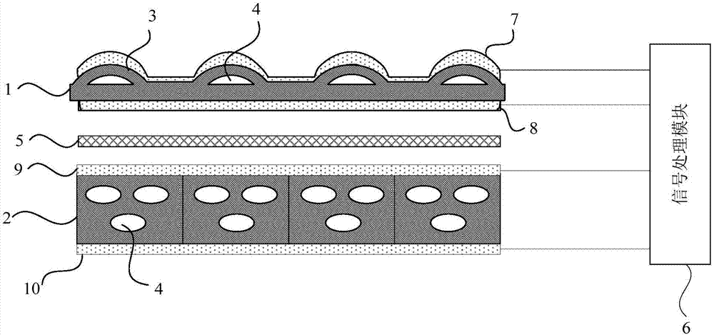
[0030] figure 1 A schematic diagram of a signal detection sensor structure provided by an embodiment of the present invention, such as figure 1 The signal detection sensing structure shown includes: the first piezoelectric electret layer 1, the second piezoelectric electret layer 2, and the first piezoelectric electret layer 1 and the second piezoelectric electret layer An adhesive layer 5 between 2; the adhesive layer 5 laminates and bonds the first piezoelectric electret layer 1 and the second piezoelectric ele...


PUM


Abstract

The invention discloses a signal detection sensing structure and a manufacturing method thereof, and a signal detection method. The signal detection sensing structure comprises a first piezoelectric electret layer, a second piezoelectric electret layer and a bonding layer located between the first piezoelectric electret layer and the second piezoelectric electret layer. One side surface of the first piezoelectric electret layer, which is far away from the second piezoelectric electret layer, comprises a plurality of embossment structures. One side surface of the second piezoelectric electret layer, which is close to the first piezoelectric electret layer, is a smooth surface. The first piezoelectric electret layer is used for detecting a contact signal and / or a slide signal of a touch object. The second piezoelectric electret layer is used for detecting a contact signal of the touch object. Through a lamination structure of the first piezoelectric electret layer and the second piezoelectric electret layer, a single sensing unit can simultaneously detect the contact signal and the slide signal. By using the signal detection sensing structure, the structure is simple; sensitivity is high; there is no pyroelectric effect; in a work temperature range, the structure is not influenced by temperature changes; and high precision detection of the contact signal and the slide signal can be realized.

Description

technical field [0001] Embodiments of the present invention relate to signal detection technology, in particular to a signal detection sensing structure, a manufacturing method thereof, and a signal detection method. Background technique [0002] The senses related to hand function mainly include contact, pressure, position, sliding, temperature, etc. The survey shows that contact and grasping are more important. In the research, we also found that "contact" and "sliding" are the two most important types of sensory information of the prosthetic hand, which exist in most prosthetic hand movements ("waving" etc. except), is the key to achieve a safe and reliable grip. The touch-slip signal can be obtained by analyzing the interaction force between the prosthetic hand and the object. Generally speaking, the "touch" signal is mainly static force, while the "slide" signal is mainly dynamic force. [0003] The most common static force sensors are capacitive and resistive sensors...

Claims


Application Information

Patent Timeline
Patent Type & Authority Applications(China)
IPC IPC(8): G01L1/16G01H11/08
CPCG01H11/08G01L1/16
Inventor 方鹏田岚李向新李光林
Owner SHENZHEN INST OF ADVANCED TECH
Learn More