Test bench for low-pressure sealing test of nuclear power instrument valve

A technology for low-pressure sealing and instrument valves, which is applied in fluid tightness testing, liquid tightness measurement using liquid/vacuum degree, machine/structural component testing, etc. It can solve the laboriousness of operators and lengthen the time spent on clamping , Hydraulic valve clamping troubles and other problems, to achieve the effect of reducing the workload

Inactive Publication Date: 2017-11-07
JIANGSU XINGHE VALVE
View PDF0 Cites 0 Cited by
  • Summary
  • Abstract
  • Description
  • Claims
  • Application Information

AI Technical Summary

Problems solved by technology

[0002] After the valve is produced and assembled, it is necessary to test various performances of the valve, such as tightness, etc. The valve test bench is a platform for testing the water pressure and air pressure parameters of pipeline valves. The equipment structure of the existing valve sealing test bench It is relatively simple, and the positioning accuracy is relatively poor, which brings troubles to the clamping of the hydraulic valve. The clamping of the traditional valve test bench is to use three-jaw clamps to press on the flange of the hydraulic valve. The position of the hydraulic valve is not positioned, but it is roughly placed on the test platform, so that when the three-jaw clamp moves to the flange, it needs to perform multiple single actions to prevent over-movement and touch the hydraulic pressure. The valve body is used to protect the paint on the valve body, and this increases the time spent on clamping, and the efficiency of positioning and clamping is extremely low, which affects the test efficiency of the valve and reduces the cost of the factory. Productivity; Another tradition is to use the screw to drive two sealing discs to move on the guide rail, and seal the inlet and outlet of the valve, which is inconvenient to use, laborious for the operator, and cannot be automatically controlled by wire
The fixed support platform of the traditional valve test bench adjusts the rise or fall of the support platform through the screw, which is inconvenient to use and cannot realize automatic control

Method used


Image

  • Test bench for low-pressure sealing test of nuclear power instrument valve
  • Test bench for low-pressure sealing test of nuclear power instrument valve
  • Test bench for low-pressure sealing test of nuclear power instrument valve

Examples


Embodiment Construction

[0020] The present invention will be further described below in conjunction with the accompanying drawings and specific embodiments.

[0021] In the description of the present invention, it should be noted that the terms "center", "upper", "lower", "left", "right", "vertical", "horizontal", "inner", "outer" etc. The indicated orientation or positional relationship is based on the orientation or positional relationship shown in the drawings, and is only for the convenience of describing the present invention and simplifying the description, rather than indicating or implying that the referred device or element must have a specific orientation, or in a specific orientation. construction and operation, therefore, should not be construed as limiting the invention. In addition, the terms "first", "second", and "third" are used for descriptive purposes only, and should not be construed as indicating or implying relative importance.

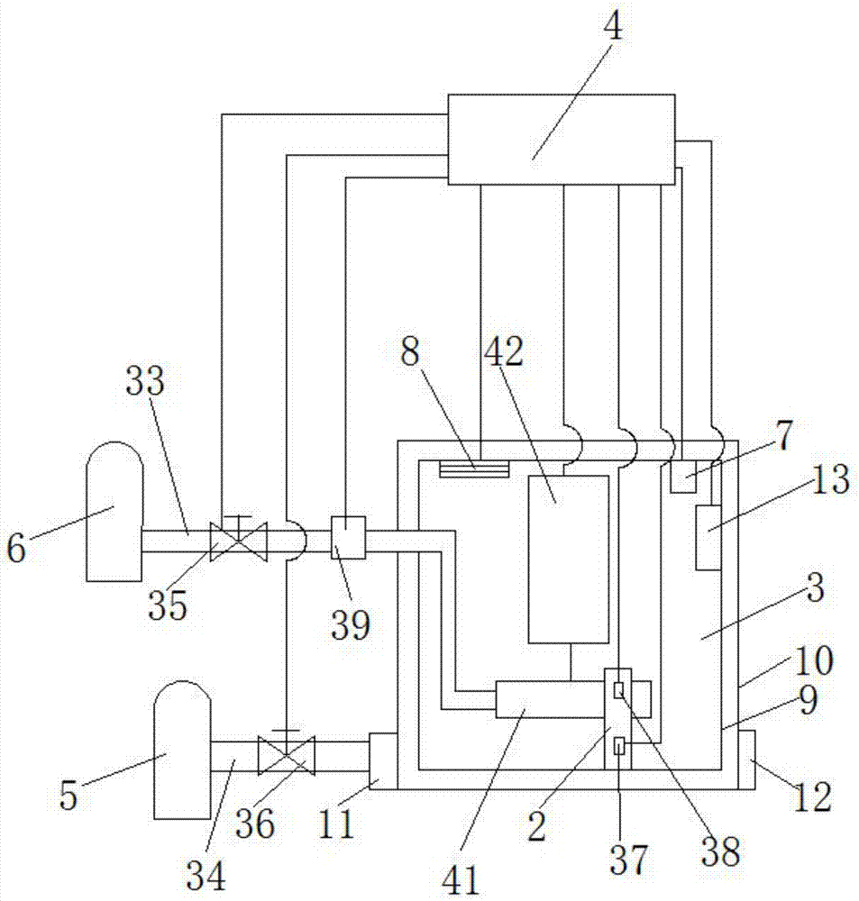
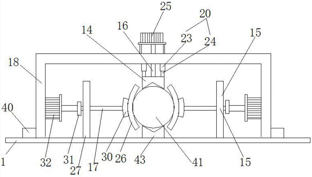
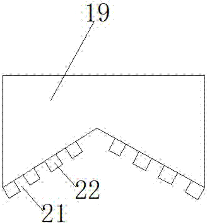
[0022] A test bench for the low-pressure sealing...


PUM


Abstract

The invention provides a test bench for low-pressure sealing test of nuclear power instrument valves. The invention adjusts the temperature of the incubator through the heater and liquid nitrogen to meet the requirements of testing the sealing performance of valves at different temperatures. At the same time, the PLC controller is used , temperature sensor, pressure sensor, and solenoid valve to realize the automation of the test process and reduce the workload; through the first fixing piece, the second fixing piece, and the V-shaped block, the clamping and fixing of the valve is realized, and the valve is fixed in the four directions of up, down, left, and right at the same time , using the PLC controller and electric push rod to realize the intelligent operation of the fixed process, saving time and effort.

Description

technical field [0001] The invention relates to the technical field of valve experiment devices, in particular to a test bench for low-pressure sealing test of nuclear power instrument valves. Background technique [0002] After the valve is produced and assembled, it is necessary to test various performances of the valve, such as tightness, etc. The valve test bench is a platform for testing the water pressure and air pressure parameters of pipeline valves. The equipment structure of the existing valve sealing test bench It is relatively simple, and the positioning accuracy is relatively poor, which brings troubles to the clamping of the hydraulic valve. The clamping of the traditional valve test bench is to use three-jaw clamps to press on the flange of the hydraulic valve. The position of the hydraulic valve is not positioned, but it is roughly placed on the test platform, so that when the three-jaw clamp moves to the flange, it needs to perform multiple single actions to...

Claims


Application Information

Patent Timeline
Patent Type & Authority Applications(China)
IPC IPC(8): G01M3/22
CPCG01M3/224
Inventor 朱义芳
Owner JIANGSU XINGHE VALVE
Why Eureka
Try Eureka