
Multi-core cable non-invasive current measurement method and measurement device

A current measuring device, a non-invasive technology, applied in the direction of measuring devices, measuring electrical variables, and only measuring current, etc., can solve the problems that the accuracy of measurement results cannot be guaranteed, the measurement accuracy is not high, and the detection is not common, so as to improve the measurement The effect of improving efficiency, reducing interference, and improving measurement accuracy

Active Publication Date: 2020-01-21
UNIV OF SCI & TECH BEIJING
View PDF6 Cites 2 Cited by
  • Summary
  • Abstract
  • Description
  • Claims
  • Application Information

AI Technical Summary

Problems solved by technology

However, due to many difficulties in the non-invasive measurement technology itself, non-invasive current detection of multi-core cables is not common at present. At the same time, the measurement accuracy is not high, the measurement efficiency is low, and the accuracy of the measurement results cannot be guaranteed.

Method used


Image

  • Multi-core cable non-invasive current measurement method and measurement device
  • Multi-core cable non-invasive current measurement method and measurement device
  • Multi-core cable non-invasive current measurement method and measurement device

Examples


no. 1 example

[0066] In this embodiment, the non-invasive current measurement method for a multi-core cable of the present invention is described by taking a double-core conductor with the same current as an example.

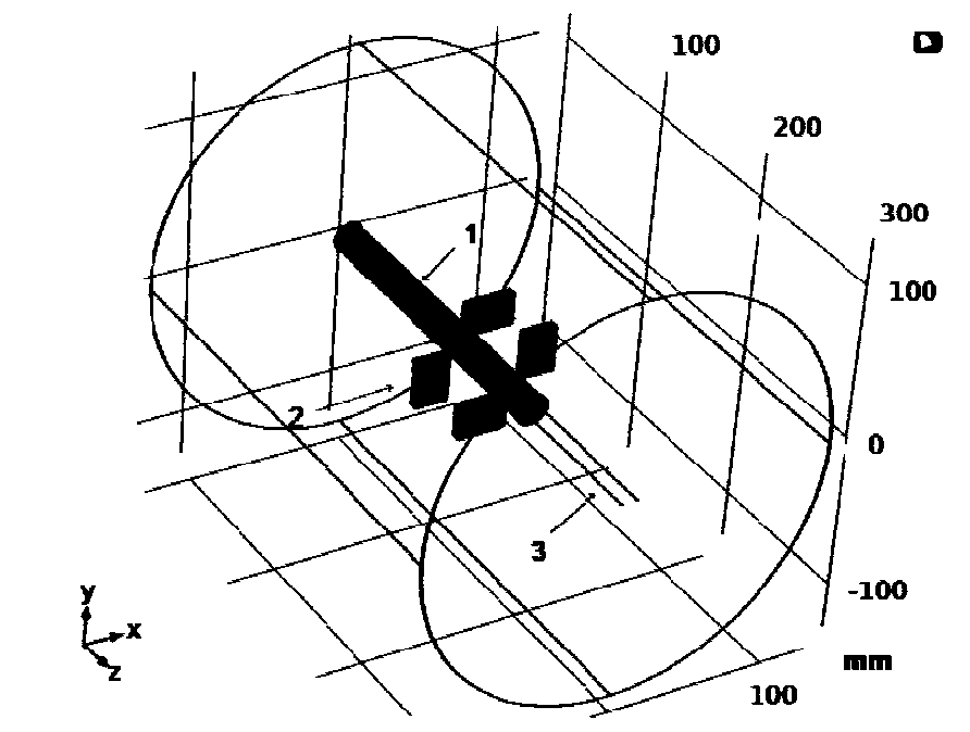
[0067] figure 1 It is a schematic diagram of the positional relationship between the multi-core cable and the magnetoresistive sensor in this embodiment. The magnetoresistive sensors in this embodiment are preferably four biaxial AMR sensors 2 , and the four biaxial AMR sensors form a detection device. Such as figure 1 As shown, the multi-core cable 1 contains two separate wires 3, and the four biaxial AMR sensors 2 are distributed in the same plane of the cross-section at any position of the cable.

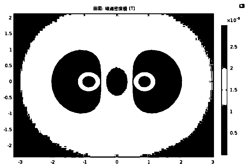
[0068] figure 2 and image 3 It is the theoretical distribution of the magnetic field around the multi-core cable in this embodiment. in, figure 2 … image 3 …

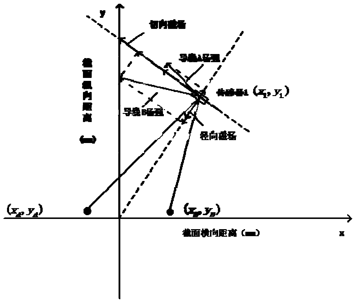
[0069] Figure 4 It is the relationship diagram of the magnetic field vector detected by the magnetoresist...

no. 2 example

[0076] Corresponding to the multi-core cable non-invasive measurement method in the first embodiment, this embodiment provides a multi-core cable non-invasive measurement device, the measurement device includes a magnetoresistive sensor, an amplifier, an ADC, and a controller; May include USB interface. Among them, the magnetoresistive sensors are four symmetrically placed biaxial AMR magnetoresistive sensors, which constitute the sensor part of the measuring device. Four symmetrical dual-axis AMR magnetoresistive sensors form a separable ring circuit board, and the center is a round hole suitable for the outer diameter of the cable, and the cable to be tested passes through the center round hole.

[0077] The ADC, the controller, and the USB interface to communicate with the computer form the digital part of the measurement setup.

[0078] The circuit board of the sensor part is connected to the digital part of the measurement device through a ribbon cable with a width of 1....


PUM


Abstract

The invention provides a multi-core cable noninvasive current measurement method and measurement device. According to the method, the tangential components and the radial components of a multi-core lead surrounding magnetic field are measured by using a magnetic resistance sensor, the obtained tangential components and the radial components of the magnetic field are analyzed through the Biot-Savart law and the position coordinates of the lead in the multi-core cable and the current value borne by the corresponding lead of the corresponding coordinates are obtained, and the measurement precision and accuracy can be further enhanced through error estimation and magnetic field intensity compensation. According to the multi-core cable noninvasive current measurement method and measurement device, detection of the multi-core cable surrounding magnetic field and noninvasive measurement of the current can be realized so that the current detection efficiency of the multi-core cable can be enhanced.

Description

technical field [0001] The invention belongs to the technical field of automatic testing, and in particular relates to a multi-core cable non-invasive current measuring method and a measuring device. Background technique [0002] Automated testing of electronic products includes measurement of different accuracy ranges in voltage, current, power, etc. Among them, current detection is the basis and key link for implementing control or status monitoring in most occasions. For example, the power grid needs to detect the fault location and load condition by detecting the current; state of the chain, etc. [0003] Current measurement is divided into intrusive measurement and non-invasive measurement. Intrusive measurement is a more commonly used current measurement technology. There are two main methods. One is to read data directly from the ammeter connected in series to the circuit, and the other is to measure the voltage on a resistor whose resistance value is known in serie...

Claims


Application Information

Patent Timeline
Patent Type & Authority Patents(China)
IPC IPC(8): G01R19/00
CPCG01R19/0092
Inventor 张勇军宋宪徐言东郝春辉
Owner UNIV OF SCI & TECH BEIJING
Learn More