Side-mounted lens set and mounting method thereof

An installation method and mirror group technology, applied in the field of mirror groups, can solve problems such as inconvenient assembly of springs, unfavorable engineering, poor controllability of lens eccentricity and inclination, etc., so as to improve precision, avoid concentrated force, and ensure stability Effect

Active Publication Date: 2017-11-07
SHANGHAI MICRO ELECTRONICS EQUIP (GRP) CO LTD
View PDF6 Cites 6 Cited by
  • Summary
  • Abstract
  • Description
  • Claims
  • Application Information

AI Technical Summary

Problems solved by technology

Considering that in actual engineering, the component is assembled horizontally and used sideways, the eccentricity and tilt of the lens are poorly controllable, and the assembly of each spring is inconvenient during integration. It is often suitable for testing and is not conducive to engineering

Method used


Image

  • Side-mounted lens set and mounting method thereof
  • Side-mounted lens set and mounting method thereof
  • Side-mounted lens set and mounting method thereof

Examples


Embodiment 1

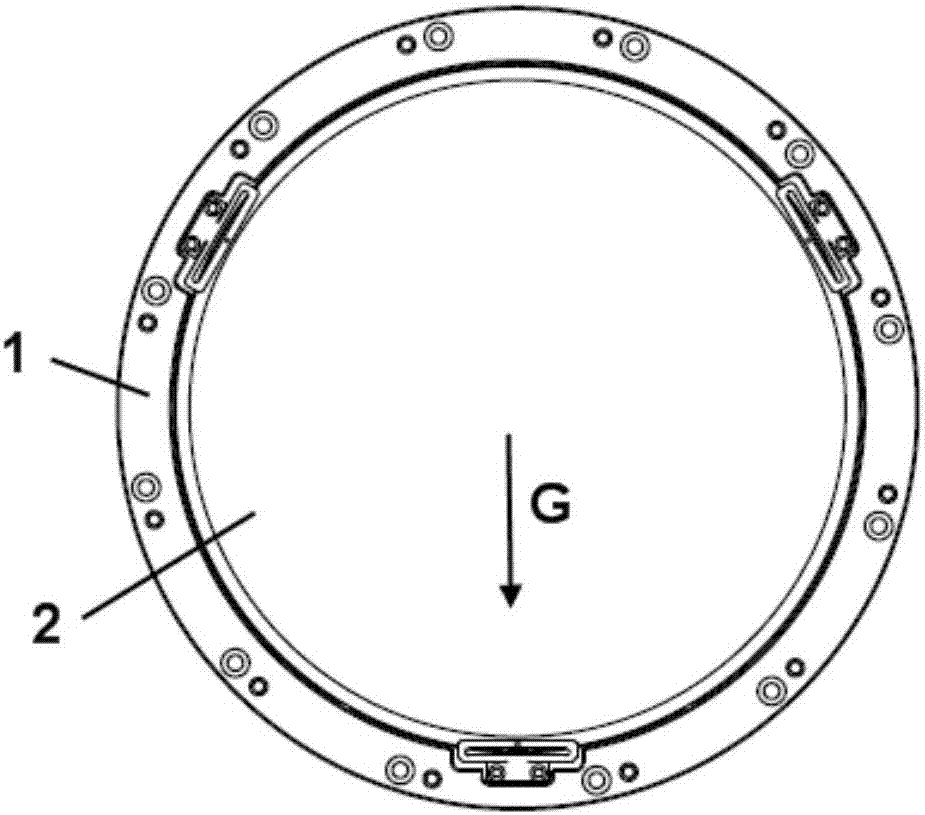
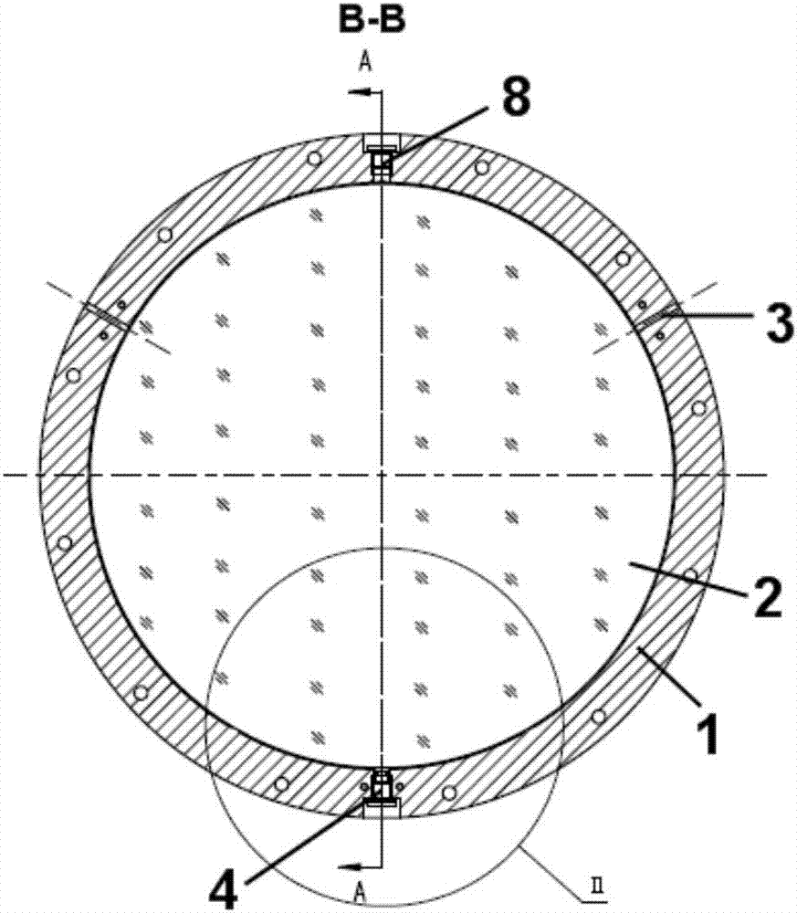
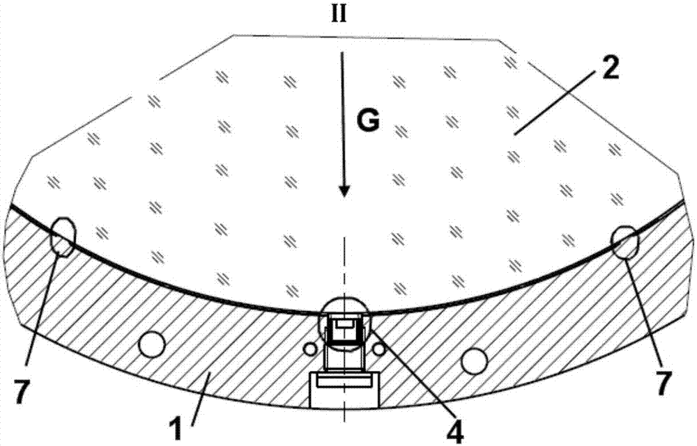
[0041] Please refer to Figure 1-5, the present embodiment 1 provides a side-standing lens group, including a side-standing picture frame 1, side-standing optical lenses 2 installed in the picture frame 1, and symmetrically distributed on both sides of the vertical center line of the picture frame 1 and The picture frame 1 is integrally formed with two hard support points 7, and each of the hard support points 7 is located below the horizontal centerline of the picture frame 1, and each of the hard support points 7 is connected to the optical The lens 2 is directly contacted and connected; an elastic support member 4 is arranged directly below the bottom of the optical lens 2, and the elastic support member 4 is contacted and connected through an adjustment screw 10 penetrating directly below the bottom of the frame 1; A compression screw 8 for limiting radial displacement of the optical lens 2 runs through the top of the mirror frame 1 .

[0042] In the side-standing lens gr...

Embodiment 2

[0048] Embodiment 2 provides a method for installing the side mirror group of Embodiment 1, including the following steps:

[0049] Step S1, setting the mirror frame 1 sideways;

[0050] Step S2, placing the optical lens 2 sideways on the hard support body 5 of the frame 1;

[0051] Step S3, by pressing the screw 8 to apply a force of the size of the gravity G of the optical lens 2 to offset the optical lens 2 against each hard support point 7, so as to limit the radial displacement of the optical lens 2;

[0052] Step S4, use a dynamometer to adjust the supporting force of the elastic support member 4 to support the optical lens 2, and make the supporting force equal to 1 / 3 of the gravity G of the optical lens 2, and tighten the adjusting screw 10;

[0053] Step S5, install more than one pre-tension reed 6 as required, and measure the force of the pre-tension reed 6 to make it equal to 2 / 3 of the gravity G of the optical lens 2;

[0054] Step S6, dispensing glue through th...


PUM


Abstract

The invention provides a side-mounted lens set and a mounting method thereof. The lens set comprises a frame, an optical lens and two hard supporting points which are symmetrically distributed at two sides of the vertical axis of the frame and are integrally formed with the frame, wherein each hard supporting point directly contacts with and is connected with the optical lens. The bottom of the optical lens is provided with an elastic supporting member in contact connection through an adjusting screw. The top of the frame is provided with a compression screw which is used for preventing axial displacement of the optical lens. The mounting method comprises the steps of placing the optical lens on the hard supporting member of the frame sideways; applying a force with a certain magnitude to the optical lens through the compression screw for making the optical lens abut against each hard supporting point; adjusting the supporting force of the elastic supporting member for supporting the optical lens, and locking the adjusting screw; mounting more than one pre-tightened reed, applying glue to glue applying holes for fixedly connecting the frame with the optical lens; and mounting an axial stopper. The side-mounted lens set and the mounting method have advantages of relatively high stability, relatively high face type precision and benefit for engineering realization.

Description

technical field [0001] The invention relates to a mirror group, in particular to a side-standing mirror group and an installation method thereof. Background technique [0002] The processing and manufacturing of high-precision optical lenses is a very complicated process. As the imaging quality of the optical system becomes higher and higher, not only the optical path becomes more and more complicated, and the number of optical components increases, but also the optical components are required to have micron-scale Positioning accuracy, while maintaining surface accuracy of ten nanometers. [0003] In catadioptric lenses, the optical axis not only has a vertical direction, but also a horizontal direction, that is, the optical element needs to be installed sideways in addition to being installed horizontally. The effect of gravity on optical elements placed horizontally is completely different from that on optical elements placed sideways. When the diameter of the optical ele...

Claims


Application Information

Patent Timeline
Patent Type & Authority Applications(China)
IPC IPC(8): G02B7/02
CPCG02B7/022G02B7/026G02B7/023G02B7/028G02B7/025
Inventor 汪明天刘国淦
Owner SHANGHAI MICRO ELECTRONICS EQUIP (GRP) CO LTD
Why Eureka
Try Eureka