A multi-mode voltage temporary-rise and temporary-drop power supply based on a three-phase inverter

A three-phase inverter, voltage swell technology, applied in the direction of AC network voltage adjustment, electrical components, harmonic reduction devices, etc., can solve problems such as slow response speed, low drop accuracy, and inability to generate waveforms of arbitrary frequencies. , to achieve the effect of fast dynamic response and high output precision

Pending Publication Date: 2017-11-07
HANGZHOU DIANZI UNIV
View PDF5 Cites 10 Cited by
  • Summary
  • Abstract
  • Description
  • Claims
  • Application Information

AI Technical Summary

Problems solved by technology

This scheme changes the parameters of the original line, and has the defects of large energy loss and low drop accuracy, and the output cannot be set arbitrarily. The topology structure based on AC electronic switches is used to simulate the actual power grid voltage swell / sag situation, and the response speed is fast, but it cannot generate waveforms of arbitrary frequencies, and the voltage cannot be automatically adjusted; the synchronous generator method is through changing the synchronous The excitation current of the generator is used to simulate the voltage drop on the load side. This solution has problems such as slow response speed and large equipment size; the method based on power electronic conversion is generally based on a three-phase inverter circuit. Further improvement, the normal and stable voltage from the power grid is converted, and the converted voltage is used to simulate the voltage swell / sag phenomenon of the power grid

Method used


Image

  • A multi-mode voltage temporary-rise and temporary-drop power supply based on a three-phase inverter
  • A multi-mode voltage temporary-rise and temporary-drop power supply based on a three-phase inverter
  • A multi-mode voltage temporary-rise and temporary-drop power supply based on a three-phase inverter

Examples


Embodiment Construction

[0020] The present invention will be further described below in conjunction with the accompanying drawings of the description.

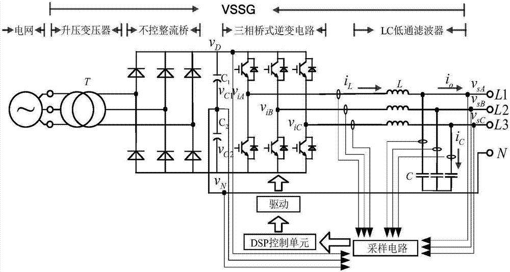
[0021] refer to figure 1 , a multi-mode voltage swell and sag power supply based on a three-phase inverter of the present invention, its power main circuit consists of a step-up transformer, a three-phase uncontrolled rectifier bridge, a DC link split capacitor, a voltage source inverter circuit, Filter reactors and filter capacitors. The control part includes sampling circuit, driving circuit and DSP control unit.

[0022] Among them, the step-up transformer is connected between the power grid and the uncontrolled rectifier bridge. The voltage loss in the transformer and filter link is generally about 105% Uh, and the power Sn depends on the actual test load P L The needs are determined. The rated current value of the uncontrolled rectifier bridge is determined by Uh and P L To be sure, the rated current of the three-phase inverter bridge needs...


PUM


Abstract

The invention discloses a multi-mode voltage temporary-rise and temporary-drop power supply based on a three-phase inverter. According to the invention, a step-up transformer raises the voltage of the general commercial electric supply to be more than the maximum voltage required for the temporary rise, and rectification is carried out through a three-phase uncontrolled rectifier bridge to provide a DC power supply for the three-phase inverter. A direct current bus split capacitor is connected between the uncontrolled rectifier bridge and a three-phase bridge type inverter circuit. The midpoint of the split capacitor is lead out to be used as an output neutral line to form a three-phase four-wire topological structure to achieve complete decoupling between output phases. Through an inverter SPWM control strategy, each gate signal is generated to control the on / off time of each switch so as to realize the independent control of the voltage of each phase and the control of the voltage deviation of the split capacitor in a DC link; the direct current is converted into an SPWM wave; and finally, an LC sine filter filters out high-frequency harmonics and outputs a sine wave that meets the specified amplitude, phase and frequency to achieve the accurately adjustable duration of the transient voltage and the accurately adjustable voltage phase and amplitude of any phase.

Description

technical field [0001] The invention relates to a low-voltage power supply generating device, in particular to a multi-mode voltage swell and sag power supply based on a three-phase inverter. Background technique [0002] In the actual power grid, voltage sags will be caused by UHV AC and DC line faults, low-frequency oscillation of the power grid, start-up of large motors, and short-circuit faults in the power supply network; Cause grid voltage swell. The demand background of the research first involves the high and low voltage ride-through problem of the frequency converter of the auxiliary equipment system of the large-scale thermal power plant. , In addition to shutdown, it will also cause damage to the frequency converter, and various situations may cause the trip of the entire generator set. This potential safety hazard that seriously threatens the stable operation of the power system has attracted great attention in the industry. In order to solve the problem of the...

Claims


Application Information

Patent Timeline
Patent Type & Authority Applications(China)
IPC IPC(8): H02J3/12H02J3/01H02M7/5395
CPCH02J3/01H02J3/12H02M7/5395Y02E40/40
Inventor 韩其国朱凯王兴全宇
Owner HANGZHOU DIANZI UNIV
Why Eureka
Try Eureka