High capacity air-cooled static var generator power unit structure

A static reactive power and power unit technology, applied in reactive power adjustment/elimination/compensation, reactive power compensation, electrical components, etc., it can solve problems such as heavy workload, water seepage, and high reliability requirements, and achieve heat dissipation. , to ensure the effect of electrical parameters

Pending Publication Date: 2017-11-07
STATE GRID HUNAN ELECTRIC POWER +2
View PDF4 Cites 2 Cited by
  • Summary
  • Abstract
  • Description
  • Claims
  • Application Information

AI Technical Summary

Problems solved by technology

[0003] At present, the large-capacity static var generators generate a large amount of heat, and the water-cooling method can effectively conduct the generated heat, and the water-cooling cooling method is mainly used, but the large-capacity static var generators with high output voltage and a large number of power devices use water cooling. The following problems exist: 1. The reliability of water cooling equipment is extremely high, and the voltage inside the large-capacity static var generator is high, so pure water with extremely low conductivity must be used, which requires pure water cooling equipment to operate continuously all year round. Whether the cooling equipment operates reliably It directly affects the operational reliability of the reactive power generator; 2. There is a risk of water seepage in water cooling. The large-capacity high-voltage static var generator is composed of a large number of power units connected in series. Accessories with excellent materials, high-quality engineering technology and water seepage alarm means, after a certain period of use, there is still a risk of water seepage; 3. The operation and maintenance workload of the water cooling system is heavy. At present, substations are implementing unattended mode, and the water cooling system requires Personnel continuously monitor and maintain the status of each moving part, and the workload is heavy. It is becoming more and more difficult to popularize and apply in substations that gradually implement the unattended operation mode

Method used


Image

  • High capacity air-cooled static var generator power unit structure
  • High capacity air-cooled static var generator power unit structure
  • High capacity air-cooled static var generator power unit structure

Examples


Embodiment Construction

[0023] The present invention will be further described in detail below in conjunction with the accompanying drawings and specific embodiments.

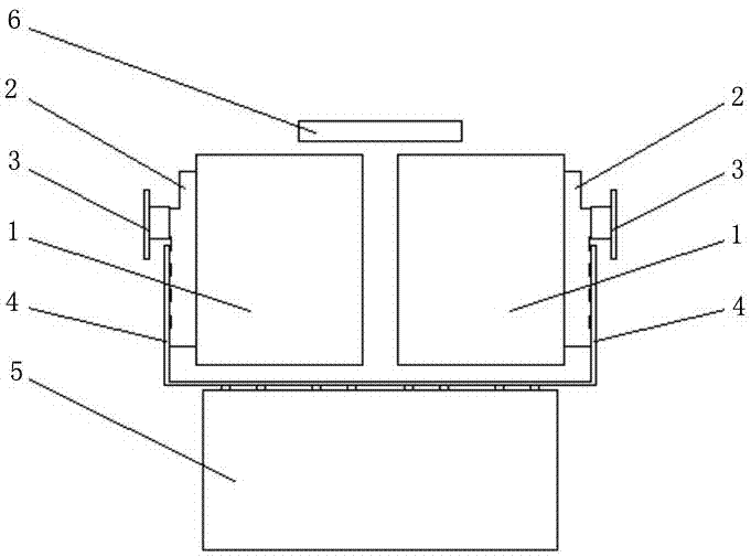
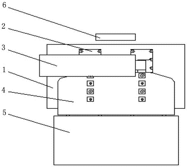
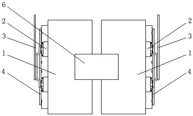
[0024] Figure 1 to Figure 5 It shows an embodiment of the power unit structure of the large-capacity air-cooled static var generator of the present invention, including two heat pipe radiators 1 arranged at intervals, and the two heat pipe radiators 1 are equipped with unit The circuit bridge arm 2, each unit circuit bridge arm 2 is connected with an AC output bar 3, and the two unit circuit bridge arms 2 are connected together with a DC laminated output busbar 4 enclosed to the bottom of the two heat pipe radiators 1, and the DC laminated output busbar 4 is connected to the bottom of the two heat pipe radiators. A capacitor component 5 is installed at the bottom of the layer output busbar 4 . In this structure, two heat pipe radiators 1 are used for air cooling and heat dissipation, which can effectively realize the heat dissipatio...


PUM


Abstract

The invention discloses a high capacity air-cooled static var generator power unit structure comprising two heat pipe radiators arranged at an interval; opposite outer side walls of the two heat pipe radiators are provided with unit circuit bridge arms; each unit circuit bridge arm is connected with an AC output bar; the two unit circuit bridge arms are commonly connected with a DC lamination output busbar enclosing to the bottoms of the two heat pipe radiators; the bottom of the DC lamination output busbar is provided with a capacitor assembly. The power unit structure is good in heat radiation efficacy, easy to control, and can effectively reduce the occupation area of the whole high capacity air-cooled static var generator.

Description

technical field [0001] The invention mainly relates to the technical field of electrical engineering, in particular to a power unit structure of a large-capacity air-cooled static var generator. Background technique [0002] Large-capacity static var generator is an important device for maintaining transient stability and steady-state regulation of the power system main network. With the maturity of technology, UHV power grids are gradually choosing large-capacity static var generators, because this product has many advantages such as fast reactive power response, small footprint, low cost, and simple operation and maintenance compared with SVC devices and synchronous condensers. . However, due to the large current and high switching frequency of devices, the heat generation of each power unit in a large-capacity static var generator requires an effective heat transfer method to realize the effective conduction of heat from power devices to the outside of the device. [00...

Claims


Application Information

Patent Timeline
IPC IPC(8): H02J3/18H01L23/427
CPCH02J3/18H01L23/427Y02E40/30
Inventor 陆佳政朱思国李波谭艳军黄清军朱远
Owner STATE GRID HUNAN ELECTRIC POWER
Why Eureka
Try Eureka