Self-excited vibration generator for oil and gas pipeline monitoring system

A monitoring system, self-excited vibration technology, applied in the direction of generators/motors, piezoelectric effect/electrostrictive or magnetostrictive motors, electrical components, etc., can solve the problems of electromagnetic interference, cut-off, and large volume of power generation devices , to achieve the effects of strong fluid adaptability, improved reliability, and strong power generation capacity

Active Publication Date: 2017-11-07
ZHEJIANG NORMAL UNIVERSITY
View PDF2 Cites 6 Cited by
  • Summary
  • Abstract
  • Description
  • Claims
  • Application Information

AI Technical Summary

Problems solved by technology

Although some of the pipeline fluid leakage and anti-theft monitoring and alarm methods proposed are relatively mature at the technical level, the application of the anti-theft monitoring system for long-distance pipelines in my country is still in its infancy and has not yet been widely used. One of the main reasons is The power supply problem of the monitoring system has not been well solved: ①The cost of laying cables is high and it is easy to be cut off by criminals, which will affect the normal operation of the monitoring system; ②The battery power supply has a limited service time and needs to be replaced frequently. The remote transmission of monitoring information cannot be completed even when it is replaced in time
In recent years, in order to meet the self-power supply requirements of related wireless sensor monitoring systems, people have proposed various forms of turbine-type micro-fluid power generation devices. The biggest problem is that the structure is complex and the volume is relatively large, which is not suitable for pipelines with small diameters. In some occasions, some structures of power generation devices still have electromagnetic interference and other phenomena, and their popularization and application are restricted to a certain extent.

Method used


Image

  • Self-excited vibration generator for oil and gas pipeline monitoring system
  • Self-excited vibration generator for oil and gas pipeline monitoring system
  • Self-excited vibration generator for oil and gas pipeline monitoring system

Examples


Embodiment Construction

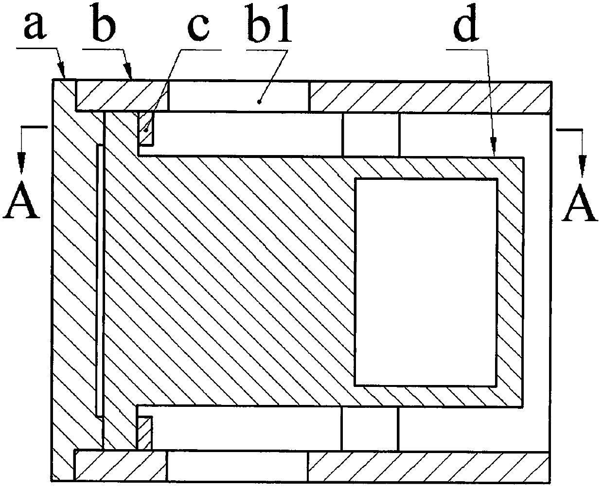
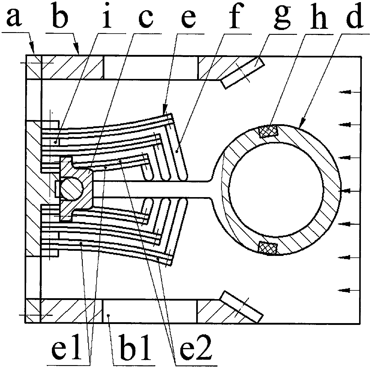
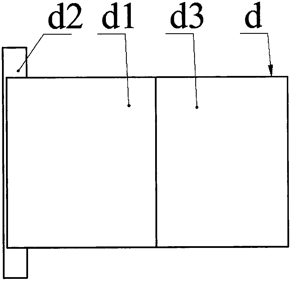
[0012] The casing b is provided with a flow hole b1, and the end is installed with a vertical plate a through screws. The vertical plate a is provided with a flow hole a1 and a boss a2. Piezoelectric vibrator e; when the number of piezoelectric vibrators e installed on one side of the boss a2 is greater than 1, a gasket i is crimped between the fixed ends of two adjacent piezoelectric vibrators e; the piezoelectric vibrator e is formed by the substrate e1 It is bonded with the piezoelectric sheet e2, and the substrate e1 of the piezoelectric vibrator e on both sides of the boss a2 is installed close to it; the other end of the piezoelectric vibrator e is installed with a top block f through screws, and the top block f is placed on the side of the piezoelectric vibrator e On one side of the base plate e1, the other end of the top block f leans against the rocker d1 of the exciter d; one end of the rocker d1 is provided with a hollow turbulent body d3, and the other end is provid...


PUM


Abstract

The invention relates to a self-excited vibration generator for an oil and gas pipeline monitoring system and belongs to the field of fluid power generation. The end portion of a housing is provided with a vertical plate having a flow passage hole and a protruded bench. The two sides of the protruded bench are provided with equal numbers of piezoelectric vibrators. A pad is pressed between the fixed ends of adjacent piezoelectric vibrators. Each piezoelectric vibrator is formed by gluing a substrate and a piezoelectric sheet. The substrates of the piezoelectric vibrators at the two sides of the protruded bench are in close installation. The other end of each piezoelectric vibrator is provided with a push block. The push blocks press against a swing arm of an exciter. One end of the swing arm is provided with a flow disturbance body, and the other end is provided with a half shaft. The half shaft is mounted on the vertical plate through a bearing base. The flow disturbance body is embedded with moving magnets. The left and right side walls of the housing are respectively provided with a fixed magnet. The moving magnets and the fixed magnets are in same pole opposite arrangement. The distance between the geometric center of each moving magnet and the center of the half shaft is equal to the distance between the geometric center of each fixed magnet and the center of the half shaft. The piezoelectric vibrator is in a flat structure before installation and in a bending structure after installation. The advantages are that the self-excited vibration generator can realize self-excited vibration power generation, is high in fluid adaptability and is simple in structure; the piezoelectric sheets only bear pressure stress, and reliability is high; and through multiple-vibrator synchronous working, power generation capacity is high.

Description

technical field [0001] The invention belongs to the technical field of pipeline fluid power generation and pipeline monitoring, and in particular relates to a self-excited vibration generator used in an oil and gas pipeline monitoring system. Background technique [0002] Due to corrosion, natural force majeure, and human theft, long-distance pipelines for long-distance fluids such as oil and natural gas often leak during use. Frequent pipeline leakage not only causes huge economic losses, but also causes damage to the surrounding natural environment. severe pollution. In the past, regular manual inspections were often used for maintenance. However, due to the long laying distance of oil and gas pipelines and the fact that they are often located in inaccessible or inaccessible places, it is difficult to detect leaks and maintain them in time by manual inspections. Therefore, various types have been proposed for pipeline leakage monitoring and anti-theft systems. Although s...

Claims


Application Information

Patent Timeline
Patent Type & Authority Applications(China)
IPC IPC(8): H02N2/18
CPCH02N2/185
Inventor 王淑云王进蔡建程
Owner ZHEJIANG NORMAL UNIVERSITY
Why Eureka
Try Eureka