High-speed parallel multi-path fractional delay filter implementation method

A technology of fractional delay and implementation method, applied in the field of communication, can solve problems such as low data rate, resource consumption, unrealistic, etc., and achieve the effect of simplifying the process of solving filter coefficients

Active Publication Date: 2017-11-07
UNIV OF ELECTRONICS SCI & TECH OF CHINA
View PDF3 Cites 4 Cited by
  • Summary
  • Abstract
  • Description
  • Claims
  • Application Information

AI Technical Summary

Problems solved by technology

[0007] Using the traditional Farrow fractional delay filter implementation method, to implement an N-order Farrow fractional delay filter, M×N multipliers are required. When the values ​​​​of N and M are large, the traditional Farrow fractional delay filter structure Very resource consuming, traditional Farrow fractional delay filter structure as attached figure 1 shown
[0008] In addition, the traditional Farrow fractional delay filter has a big defect, that is, it can only be applied to single-channel (single-channel data input, single-channel data output), low data rate application scenarios, if the front-end ADC If the sampling rate reaches 1GHz or more, then according to the traditional Farrow fractional delay filter implementation method, the working clock of the entire system is required to be above 1GHz, which is unrealistic in actual FPGA and DSP applications

Method used


Image

  • High-speed parallel multi-path fractional delay filter implementation method
  • High-speed parallel multi-path fractional delay filter implementation method
  • High-speed parallel multi-path fractional delay filter implementation method

Examples


Embodiment 1

[0059] In the present invention, the amount of delay compensation is 0.5T s , Performance simulation of applications under parallel 4-way conditions.

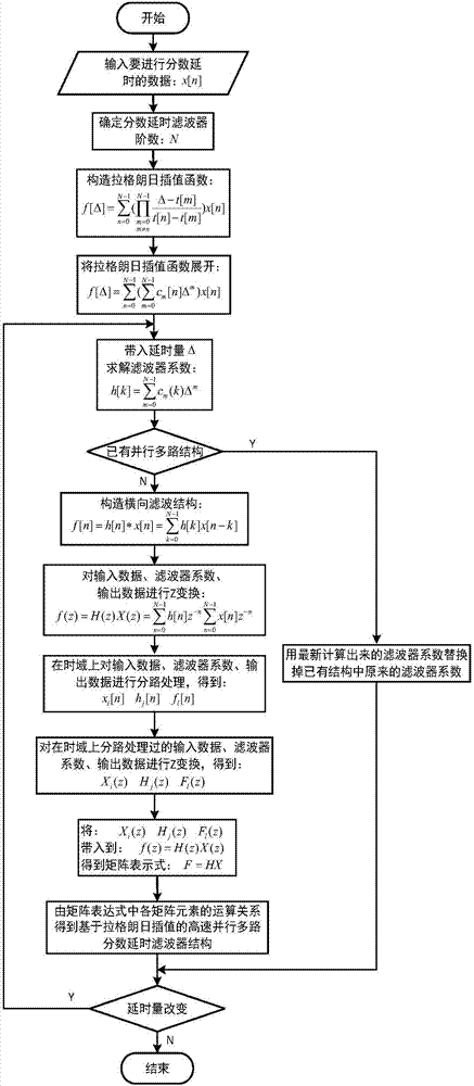
[0060] The implementation method and specific process of embodiment 1 are as attached image 3 shown.

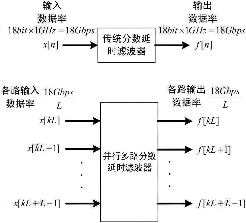
[0061] Consider a single-frequency cosine signal with a frequency of f=100MHz, assuming that the ADC at the receiving end is 18 bits, and the sampling rate is f s =1GHz, sampling period T s =1ns, the number of sampling points is D=1000.

[0062] Because the data rate after sampling is very high (18bit×1GHz=18Gbps), if the traditional serial single-way fractional delay filter implementation method is used, the entire system is required to work at a clock frequency of 1GHz, which is unrealistic. It is difficult to realize in FPGA and DSP, so the traditional serial single-channel fractional delay filter implementation method cannot be applied. Therefore, we adopt the implementation scheme of the present invention to divide ...

Embodiment 2

[0103] The present invention has the performance of performing parallel 4-way fractional delay compensation on the target signal under the condition of different delay amounts.

[0104] The method of embodiment 2 is attached figure 2 As shown, the value of delay Δ is: Δ={0.1T s 0.2T s … 0.9T s}, and the rest of the simulation conditions are the same as those in Example 1. After changing the simulation conditions, perform the steps in Example 1, and record the rms corresponding to each value of the delay value Δ, and you can get the attached Figure 5 .

[0105] From attached Figure 5 It can be seen that the delay is 0.3T s The maximum delay compensation error is 2.4378×10 -4 , the delay is 0.9T s The minimum compensation error is 3.1523×10 -5 . Generally speaking, the present invention can complete parallel 4-way to the target signal, and the amount of delay is: Δ={0.1T s 0.2T s … 0.9T s}'s delay compensation and the compensation effect works very well.


PUM


Abstract

The invention belongs to the technical field of communication, and relates to a high-speed parallel multi-path fractional delay filter implementation technology based on Lagrange interpolation. According to the invention, a fractional delay filter can be applied under the high-speed parallel multi-path condition and meanwhile, by using a Lagrange interpolation algorithm, the process of solving a filter coefficient is simplified. The high-speed parallel multi-path fractional delay filter implementation technology based on Lagrange interpolation, which is disclosed by the invention, is suitable to implement in high-speed platform, such as a FPGA, a DSP and the like, and is convenient for practical application.

Description

technical field [0001] The invention belongs to the technical field of communication, and relates to a high-speed parallel multi-path fractional delay filter realization technology based on Lagrange interpolation. Background technique [0002] The core of broadband beamforming technology is to control the delay of signals in the array to offset the spatial delay of signals from different directions, so that the signals between each array element can be added in phase to obtain beam pointing and directional gain. The high cost, bulky size, high power consumption, and poor stability of analog delay lines are not conducive to practical applications, but delay compensation in the digital domain has the advantages of low cost, high precision, and good stability, and has a good application prospect. In the digital domain, it is very easy to implement a delay that is an integer multiple of the sampling period. For the case of implementing a fractional delay of the sampling period, ...

Claims


Application Information

Patent Timeline
Patent Type & Authority Applications(China)
IPC IPC(8): H03H17/00
CPCH03H17/0018
Inventor 陶书豪甘露梁先明廖红舒
Owner UNIV OF ELECTRONICS SCI & TECH OF CHINA
Why Eureka
Try Eureka