Slow cooker with lock catch structures

A slow cooker and locking technology, which is applied to the structure of cooking utensils, cooking utensil lids, cooking utensils, etc., can solve the problems of inconvenient storage and storage, complex locking structure, and increased weight of the lid, so as to save space and maintain overall Simple appearance and improved aesthetics

Active Publication Date: 2017-11-10
SUZHOU BAOSHENG ELECTRICAL APPLIANCES CO LTD
View PDF11 Cites 0 Cited by
  • Summary
  • Abstract
  • Description
  • Claims
  • Application Information

AI Technical Summary

Problems solved by technology

[0004]However, it can be seen from the figure that the locking structure for locking the glass cover is relatively complicated, especially concentrated on the glass cover, which increases the weight of the cover , it is inconvenient to clean; in addition, the handle of the shell is a fixed structure, which brings inconvenience to storage and takes up a lot of space

Method used


Image

  • Slow cooker with lock catch structures
  • Slow cooker with lock catch structures
  • Slow cooker with lock catch structures

Examples


Embodiment 1

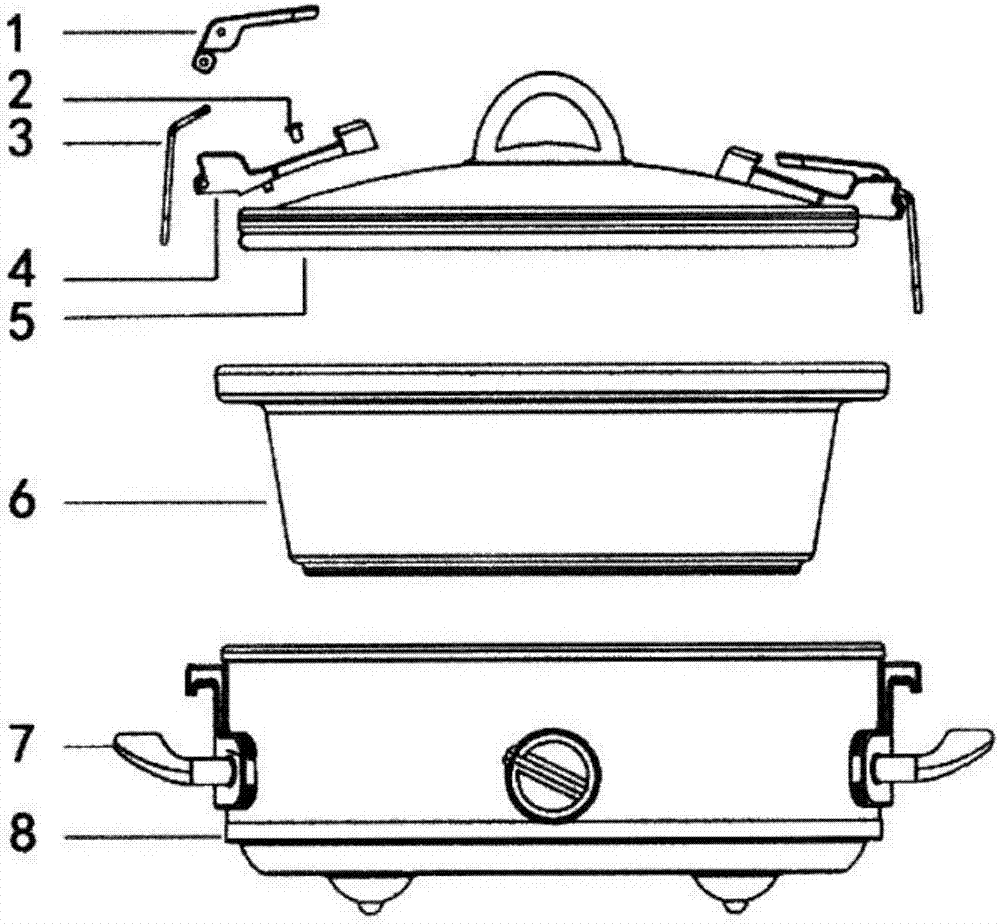
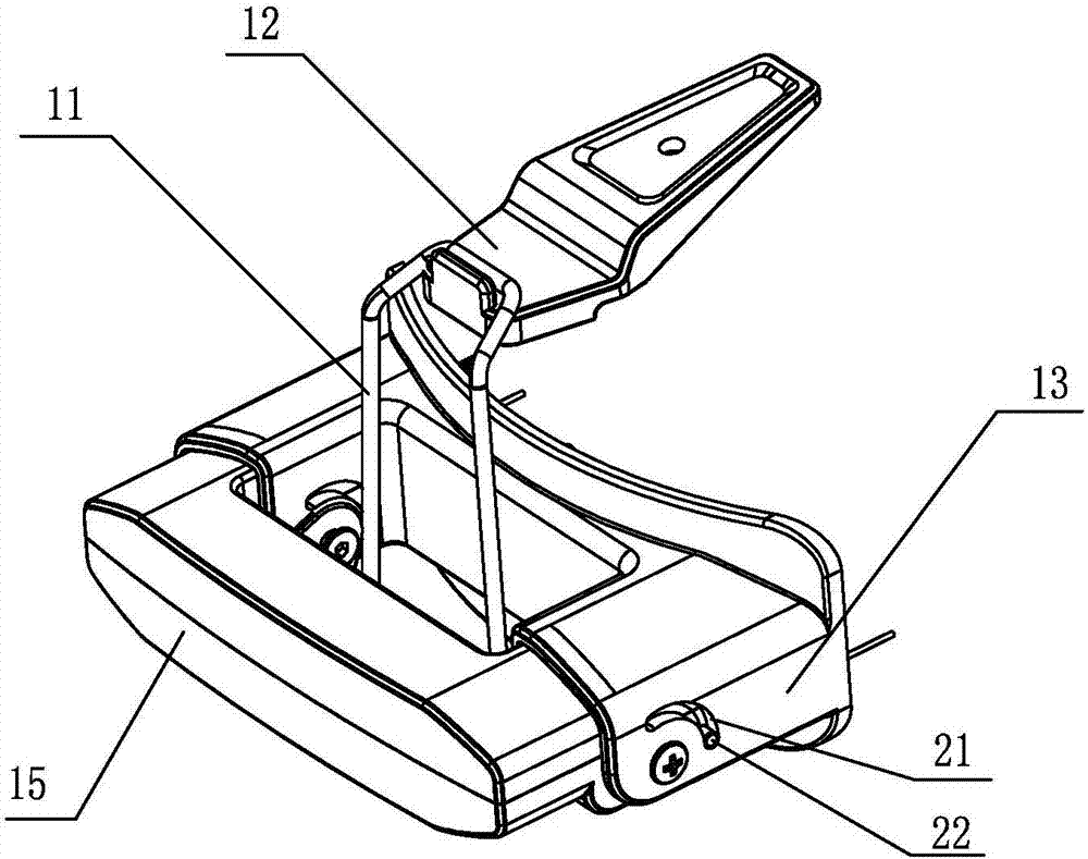
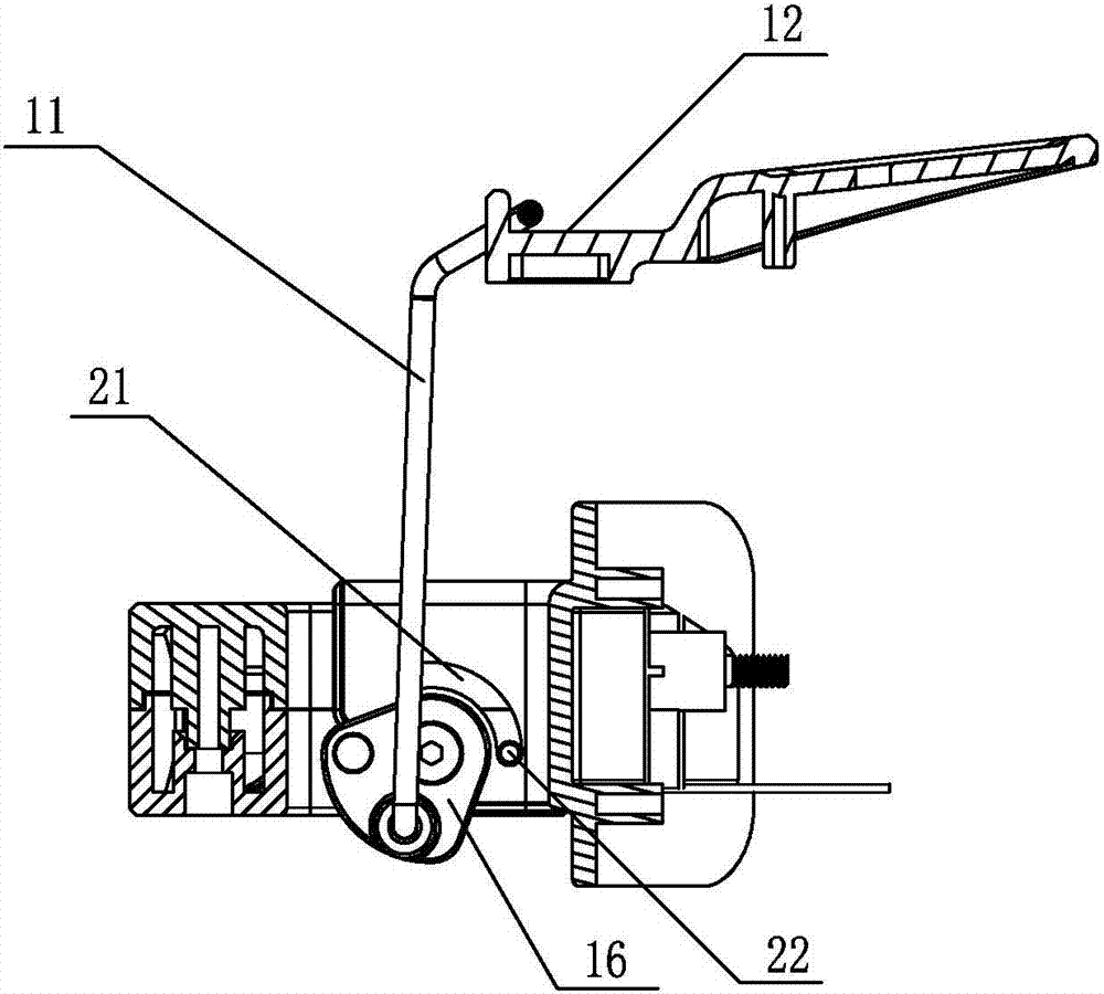
[0033] Embodiment one: see Figure 2-6 As shown, a slow cooker with a lock structure includes a pot body, a pot cover, and handles arranged on both sides of the pot body. Each of the handles is respectively provided with a lock structure, and the lock structure includes The clasp 11 installed on the handle, and the clasp 12 arranged on the pot cover, one side of the clasp 11 is an open end, and the other side is a closed end snap-fitted with the clasp 12; The handle includes a fixed portion 13 connected to the pot body, and a folding portion 15 connected to the fixed portion 13 through a rotating shaft 14. A cam mechanism 16 is provided on the rotating shaft 14 of the folding portion 15. The opening of the buckle 11 The end is arranged on the follower of the cam mechanism 16, so that there are two states of locking and unlocking between the clasp 11 and the clasp 12.

[0034] In this embodiment, the buckle 11 is formed by bending a steel wire, and its open ends are respective...

Embodiment 2

[0041] Embodiment two: see Figure 7-9 As shown, a slow cooker with a locking structure, the structure of this embodiment is basically similar to the first embodiment, the difference is that a safety lock 23 is provided in the folding part 15, and the safety lock 23 includes Support 24, spring 25 and button 26, described support 24 front end is provided with lock hole 27, is provided with the dead tongue (not drawn) that cooperates with lock hole 27 in described fixed part 13, and the middle part of described support 24 is provided with a The pressing piece 28 , one end of the spring 25 abuts against the pressing piece 28 , and the other end abuts against the button 26 , and the button 26 protrudes from the outer surface of the folding portion 15 .

[0042] In this embodiment, the cooperation between the clasp 11 and the clasp 12 is the same as that of the first embodiment, the difference is the safety lock 23 for preventing mistaken overturning, such as Figure 9 As shown, t...


PUM


Abstract

The invention discloses a slow cooker with lock catch structures. The slow cooker comprises a cooker body, a cooker cover and handles arranged on the two sides of the cooker body, and is characterized in that each handle is provided with one lock catch structure; each lock catch structure comprises a buckle ring arranged on the corresponding handle and a buckle hook arranged on the cooker cover; one side of each buckle ring is an open end, and the other side of each buckle ring is a closed end matched with the corresponding buckle hook in a buckled mode; each handle comprises a fixing part which is connected with the cooker body and a folding part connected with the fixing part through a rotating shaft; a cam mechanism is arranged on the rotating shaft of each folding part, and the open end of each buckle ring is arranged on a driven piece of the corresponding cam mechanism, so that two states of locking and unlocking are achieved between the buckle rings and the buckle hooks. The lock catch structures and the handles are combined, so that the structure of the whole cooker body is simplified, the production cost is reduced, the slow cooker is more convenient to use, and the overall attractiveness is improved.

Description

technical field [0001] The invention relates to a slow cooker, in particular to a slow cooker with a locking structure. Background technique [0002] Without a doubt, the biggest advantage of a slow cooker is that it can work all day without human supervision. When the slow cooker is working, there is no need to stir it at all. If it is stirred, the slow cooker will take a long time to regenerate the heat lost due to the lid being lifted. Busy people, whether they are office workers or stay-at-home parents, are drawn to this style of cooking. It can bring great convenience to people. As long as people prepare the ingredients in the morning, they can enjoy the ready-made food when they go home, which makes the slow cooker, a new type of cooking utensil, more and more appear in the kitchens of ordinary families. [0003] At present, the lid of our common slow cooker is separated from the porcelain pot, and the sealing performance is relatively poor, and steam will leak out w...

Claims


Application Information

Patent Timeline
Patent Type & Authority Applications(China)
IPC IPC(8): A47J27/00A47J36/10A47J45/06
CPCA47J27/002A47J36/10A47J45/06
Inventor 陆蔚岭
Owner SUZHOU BAOSHENG ELECTRICAL APPLIANCES CO LTD
Why Eureka
Try Eureka