Modelling method for phase contact area structure-activity adjusting and controlling model for micro-interface enhanced reactor
A model modeling, reactor technology, applied in chemical instruments and methods, chemical methods for reacting liquids and gaseous media, and reactions of liquids and gases under foam/aerosol/bubble, etc., can solve the problem of microbubble equipment Problems such as high energy consumption and manufacturing cost, and difficulty in universal application
- Summary
- Abstract
- Description
- Claims
- Application Information
AI Technical Summary
Problems solved by technology
Method used
Image
Examples
Embodiment 1
[0322] This example illustrates the modeling method of the phase interface area structure-effect control model of the present invention.
[0323] The phase boundary area a is one of the key characteristic parameters of the gas-liquid reaction system. The mathematical modeling of a should be objectively aimed at the system with a certain discrete distribution of the particle size of the bubbles (droplets). A large number of experiments and theoretical studies have shown that the particle size of the bubbles (a certain liquid droplet) in the heterogeneous reactor is distributed in a discrete logarithmic normal distribution. Therefore, this paper assumes that this distribution generally exists in various heterogeneous reactors, and there are m types of bubble sizes.
[0324] For the convenience of mathematical processing, it is assumed that the particle size of the bubbles in the system is continuously distributed, and thus the continuous function form of a is obtained, and then ...
Embodiment 2
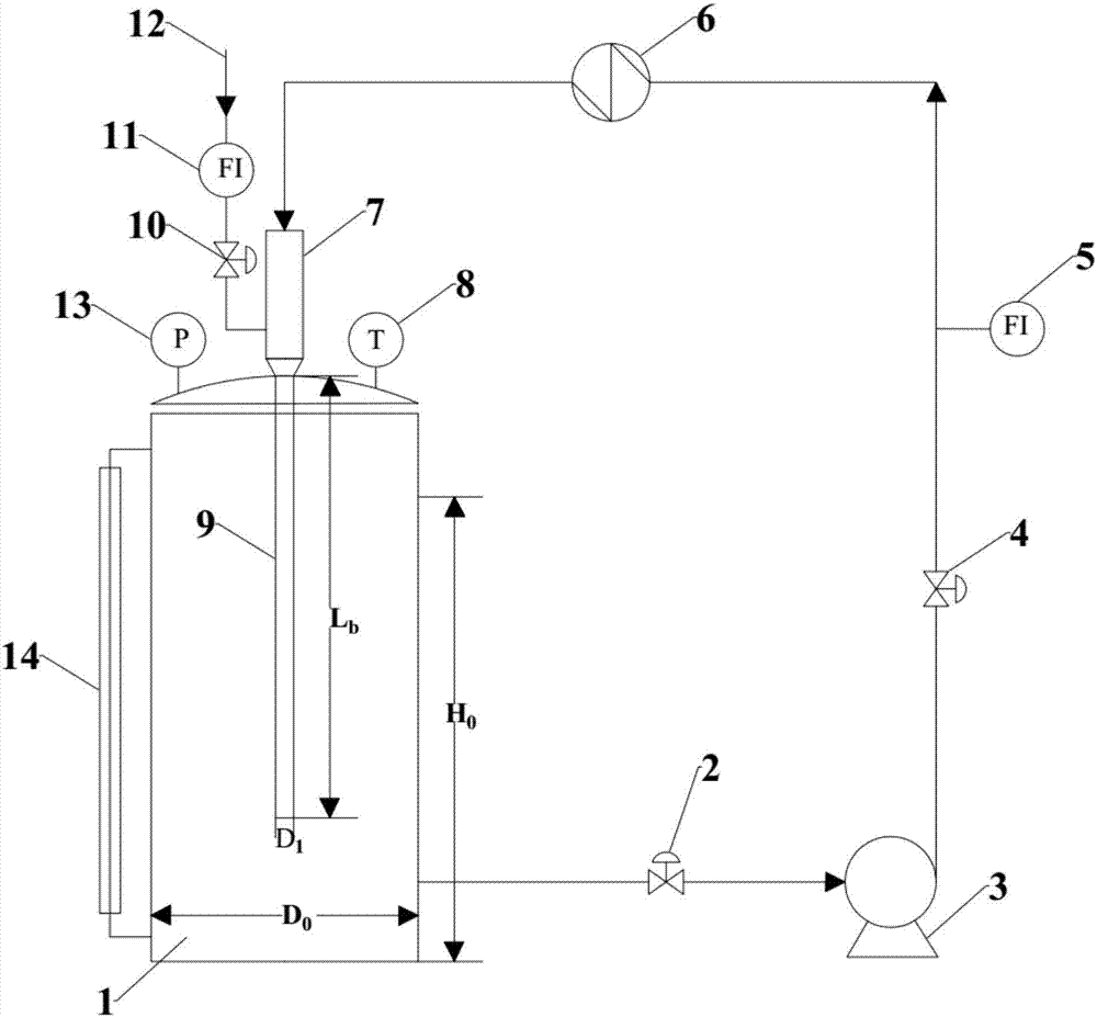
[0552] This embodiment takesfigure 1 The reactor shown is taken as an example to illustrate the application of the model constructed by the modeling method described in Example 1 in the carbon dioxide and water system reactor. figure 1 The structure of the reactor can be the structure of the existing micro-interface strengthening reactor, and only the method of the present invention is used for parameter design, and the structure of the reactor is not described in detail in the present invention.
[0553] The structure-effect control model of phase interface area is constructed as follows:
[0554]
[0555]
[0556]
[0557]
[0558]
[0559]
[0560]
[0561] d min =11.4(μ L / ρ L ) 0.75 ε -0.25 (67)
[0562] d max =0.75(σ L / ρ L ) 0.6 ε -0.4 (70)
[0563]
[0564]
[0565]
[0566] In the formula, d 32 is the average Sauter diameter of bubbles in the reactor, m; d min 、d max are the largest and smallest bubble diameters in the rea...
Embodiment 3
[0580] This embodiment takes figure 1 The reactor shown is taken as an example to illustrate the application of the model constructed by the modeling method described in Example 1 in the air-water system reactor, compared with the bubble phase interface area a produced by the existing device.
[0581] Table 3 and Table 4 are the comparison of each parameter under different particle sizes of the same system:
[0582] Table 3 Parameters calculated by the model formula under different particle sizes
[0583]
[0584] Table 4 Three kinds of resistance (air film, liquid film, intrinsic) calculated by the model formula under different particle sizes
[0585]
[0586] As shown in Table 3 and Table 4, under the same conditions, the diameter of bubbles produced by MIR is only 0.1mm, which is 1 / 10 of the original, compared with the bubbles produced by traditional reactors with a minimum diameter of 1mm. The product increases by about 467 times, the macroscopic reaction rate incr...
PUM
 Abstract
Description
Claims
Application Information
 - R&D
- Intellectual Property
- Life Sciences
- Materials
- Tech Scout
- Unparalleled Data Quality
- Higher Quality Content
- 60% Fewer Hallucinations
Browse by: Latest US Patents, China's latest patents, Technical Efficacy Thesaurus, Application Domain, Technology Topic, Popular Technical Reports.
© 2025 PatSnap. All rights reserved.Legal|Privacy policy|Modern Slavery Act Transparency Statement|Sitemap|About US| Contact US: help@patsnap.com


