Eureka AIR delivers breakthrough ideas for toughest innovation challenges, trusted by R&D personnel around the world.

Automobile flasher circuit and circuit for improving automobile flasher electromagnetic compatibility

An electromagnetic compatibility and flasher technology, applied in optical signals, vehicle components, signal devices, etc., can solve the problems that the flasher cannot meet the three-level requirements, electromagnetic induction interference, high-frequency noise interference, etc., and avoid electromagnetic induction interference. , the circuit cost is low, the effect of improving safety

Active Publication Date: 2017-11-10
ANHUI JIANGHUAI AUTOMOBILE GRP CORP LTD
View PDF4 Cites 0 Cited by
  • Summary
  • Abstract
  • Description
  • Claims
  • Application Information

AI Technical Summary

Problems solved by technology

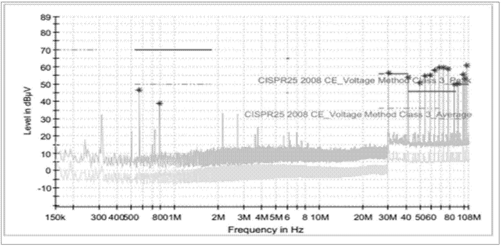
[0003] The inventor finds in the process of realizing the present invention: the electromagnetic interference source of the automobile flasher is usually the relay coil of the automobile flasher, that is, at the moment when the power supply of the automobile flasher circuit is disconnected, the relay coil will generate a higher induced electromotive force, and the induction The electromotive force will not only produce electromagnetic induction interference, but may also cause sparks or arc interference between contacts. figure 1 shown by figure 1 It can be seen that there is not only high-frequency noise interference in the frequency band above 30MHz, but also instantaneous peak current in some frequency bands.
It can be seen from the above description that the current car flasher can not meet the third-level requirements of the GB / T 18655-2010 standard proposed by the country.

Method used


Image

  • Automobile flasher circuit and circuit for improving automobile flasher electromagnetic compatibility
  • Automobile flasher circuit and circuit for improving automobile flasher electromagnetic compatibility
  • Automobile flasher circuit and circuit for improving automobile flasher electromagnetic compatibility

Examples


Embodiment Construction

[0013] Exemplary embodiments of the present disclosure will be described in more detail below with reference to the accompanying drawings. Although exemplary embodiments of the present disclosure are shown in the drawings, it should be understood that the present disclosure may be embodied in various forms and should not be limited by the embodiments set forth herein. Rather, these embodiments are provided for more thorough understanding of the present disclosure and to fully convey the scope of the present disclosure to those skilled in the art.

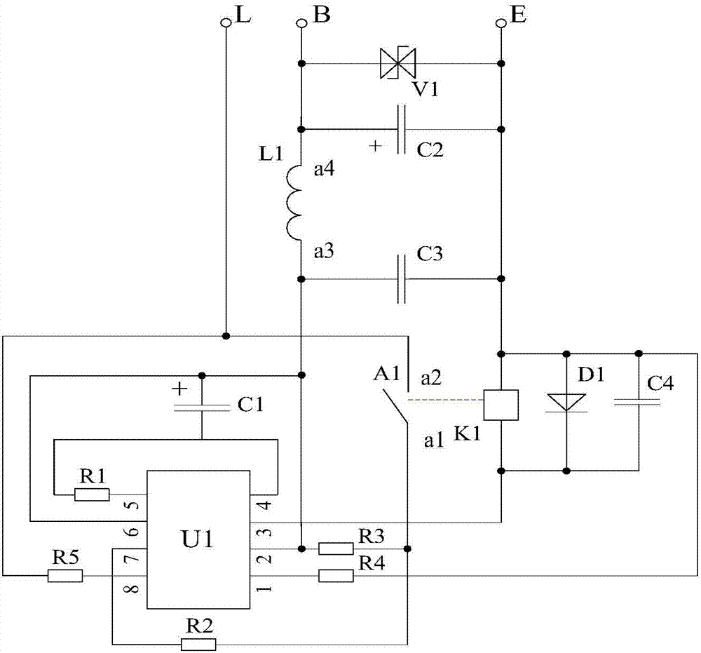
[0014] The structure of the car flasher circuit comprising the circuit for improving the electromagnetic compatibility performance of the car flasher of the present embodiment is as follows: figure 2 shown.

[0015] figure 2 Among them, the car flasher circuit of this embodiment includes three external terminals, and the car flasher is connected with external devices through these three external terminals; Control terminal L. ...


PUM


Abstract

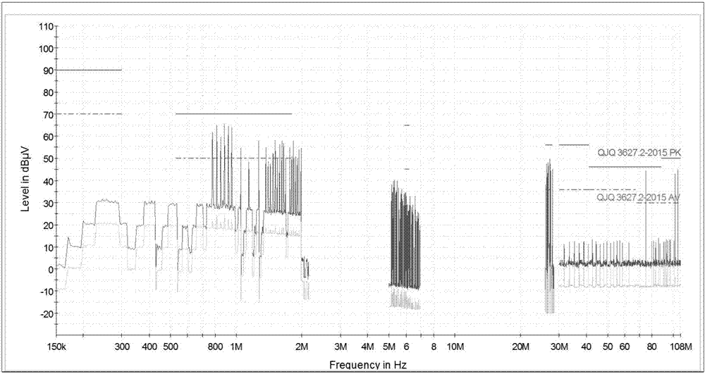
The invention discloses an automobile flasher circuit and a circuit for improving automobile flasher electromagnetic compatibility. The circuit for improving the automobile flasher electromagnetic compatibility comprises a fast recovery diode and a fourth capacitor; the fast recovery diode and an automobile flasher relay coil are connected in parallel, the positive pole of the fast recovery diode is connected with the power source grounded end, and the negative pole of the fast recovery diode is connected with a flasher integrated circuit relay control pin; and the fourth capacitor is connected with the automobile flasher relay coil in parallel and is connected with the fast recovery diode in parallel, the positive pole of the fourth capacitor is connected with the power source grounded end, and the negative pole of the fourth capacitor is connected with the flasher integrated circuit relay control pin. By means of the automobile flasher circuit and the circuit, high-frequency noise jamming and instant peak current can be effectively filtered, and the automobile flasher can meet the nationally-provided GB / T18655-2010 standard three-level requirement. The invention further has the beneficial effects that the circuit cost is low, adopted components and parts are mature, the performance is stable, the circuit assembly process is simple, and application and popularization are easy.

Description

technical field [0001] The invention relates to circuit technology, in particular to a car flasher circuit and a circuit for improving the electromagnetic compatibility performance of the car flasher. Background technique [0002] At present, the number of electronic devices in automobiles (especially new energy vehicles) is increasing, which makes the electromagnetic environment in the car increasingly complex. Since the electromagnetic waves in the working environment of the car will have adverse effects on the electronic equipment in the car, the electromagnetic compatibility performance of the electronic equipment in the car should meet certain requirements. For example, the electromagnetic compatibility performance of the car flasher should meet GB / T 18655- 2010 standard. The electromagnetic compatibility performance of the car flasher refers to the ability of the car flasher to operate in accordance with the requirements in its electromagnetic environment without caus...

Claims


Application Information

Patent Timeline
IPC IPC(8): B60Q11/00B60Q1/46B60Q1/34
CPCB60Q1/34B60Q1/46B60Q11/007
Inventor 郑芳芳李娟关宁朱先如刘盈清李洋刘兰骏
Owner ANHUI JIANGHUAI AUTOMOBILE GRP CORP LTD
Why Eureka
Eureka Blog
Learn More