

Fluid separation device, shaft structure and method of producing oil or natural gas
A separation device and fluid technology, applied in earthwork drilling, sealing/isolation, wellbore/well components, etc., can solve problems affecting oil or natural gas extraction efficiency, improve extraction efficiency, increase production efficiency, reduce damage force area effect
- Summary
- Abstract
- Description
- Claims
- Application Information
AI Technical Summary
Problems solved by technology
Method used
Image

Examples
Embodiment 1
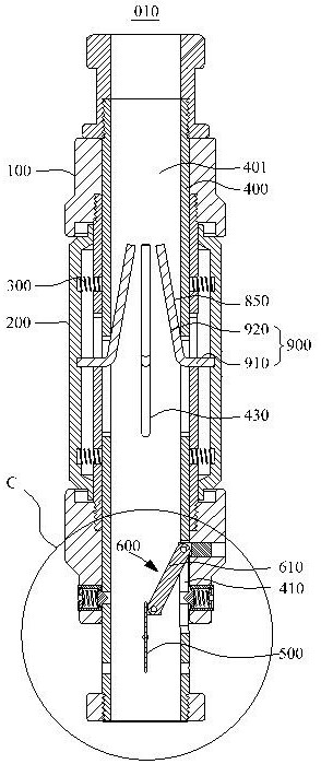
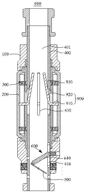
[0050] Please refer to Figure 1a-Figure 1f as well as figure 2 . among them: Figure 1a-Figure 1c A process diagram of the fluid separating device 010 provided in this embodiment from an open state to a closed state; Figure 1d-Figure 1f A process diagram of the fluid separating device 010 provided in this embodiment from a closed state to an open state; figure 2 for Figure 1a Enlarged view of C.
[0051] In this embodiment, the fluid separation device 010 includes a cylinder 100, a partition 200, a first elastic member 300, a core tube 400, a valve plate 500 and a control device 600. The plurality of partitions 200 are arranged around the axis of the cylinder 100. The partition 200 is located outside the cylinder 100. The first elastic member 300 is disposed between the partition member 200 and the cylinder 100. Along the radial direction of the cylinder 100, the first elastic member 300 exerts a radially outward elastic force on the partition 200 so that the partition 200 ...
Embodiment 2
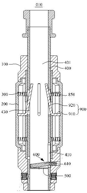
[0063] This embodiment provides a fluid separation device 010 and a well structure 020. The fluid separation device 010 and the hoistway structure 020 provided in this embodiment are basically the same as those in Embodiment 1, except that the valve plate 500 and the control device 600 are different. This embodiment mainly describes the valve plate 500 and the control device 600, and the rest of the parts can be referred to Embodiment 1, which will not be repeated in this embodiment.
[0064] Please refer to Figure 4a-Figure 4f . among them: Figure 4a-Figure 4c It is a partial structural schematic diagram of the fluid separating device 010 provided in this embodiment from an open state to a closed state; Figure 4d-Figure 4f It is a partial structural schematic diagram of the fluid separating device 010 provided in this embodiment that is converted from the closed state to the open state.
[0065] In this embodiment, the core tube 400 is provided with a first elongated hole 410 ...
Embodiment 3
[0071] This embodiment provides a fluid separation device 010 and a well structure 020. The fluid separation device 010 and the hoistway structure 020 provided in this embodiment are basically the same as those in Embodiment 1, except that the valve plate 500 and the control device 600 are different. This embodiment mainly describes the valve plate 500 and the control device 600, and the rest of the parts can be referred to Embodiment 1, and details are not described in this embodiment.
[0072] Please refer to Figure 5a-Figure 5f . among them: Figure 5a-Figure 5c It is a partial structural schematic diagram of the fluid separating device 010 provided in this embodiment from an open state to a closed state; Figure 5d-Figure 5f It is a partial structural schematic diagram of the fluid separating device 010 provided in this embodiment that is converted from the closed state to the open state.
[0073] In this embodiment, the core tube 400 is provided with a first elongated hole ...
PUM
 Abstract
Description
Claims
Application Information