Modeling structure and casting method for manufacturing large floating type ingot mold

A steel ingot mould, a large-scale technology, is applied to the modeling structure and casting field of making large-scale floating steel ingot moulds, which can solve the problems of low production efficiency, unable to meet delivery requirements, high production costs, and long mold production cycles, etc., and achieve savings The production cycle, the reduction of porosity defects, and the effect of reducing the difficulty of cleaning

Pending Publication Date: 2021-12-21
黄石新兴管业有限公司
View PDF5 Cites 0 Cited by
  • Summary
  • Abstract
  • Description
  • Claims
  • Application Information

AI Technical Summary

Problems solved by technology

Traditional casting uses wooden core boxes and steel plate tailor-welded outer molds. After molding, core making, and assembly, casting is formed. The mold production cycle is long, the cost is high, and the production efficiency is low and cannot meet the delivery requirements.
The traditional casting adopts the bottom pouring stepped pouring system. The bulge on the inner wall of the ingot mold caused by the direct flushing of the core by the inner runner is not easy to clean and smooth, and the pouring system is distributed on the outside of the ingot mold. The sand and iron ratio of the ingot mold is relatively high, and the production cost remains high.
[0003] For example, the Chinese utility model patent (publication number: CN207358114U) disclosed a pouring system for large thick-walled steel ingot mold castings in 2018. It has a foam mold, and the foam mold is covered with resin sand. The left and right sides of the foam mold are arranged symmetrically. Set of pouring system, the top of the pouring system is provided with a sprue cup, and the sprue is provided under the sprue cup, and the sprue is provided with a first layer of runners, a second layer of horizontal Sprue and the third layer runner, an inner runner is arranged beside the first layer runner, the second layer runner and the third layer runner, and the inner runner is connected with the foam mold connected, the top of the foam mold is arranged with a number of exhaust and slagging risers and open feeding risers along the circumference, and each of the two sides of the open feeding riser is provided with an exhaust and slagging riser; The new three-layer stepped pouring system adopts bottom injection + middle injection + top injection, and the inner runner directly flushes the core, which is likely to cause various defects in the ingot mold

Method used


Image

  • Modeling structure and casting method for manufacturing large floating type ingot mold
  • Modeling structure and casting method for manufacturing large floating type ingot mold
  • Modeling structure and casting method for manufacturing large floating type ingot mold

Examples


Embodiment 1

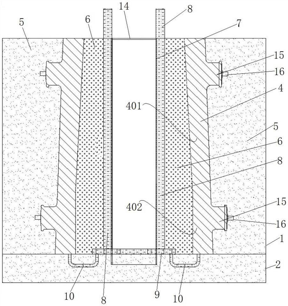
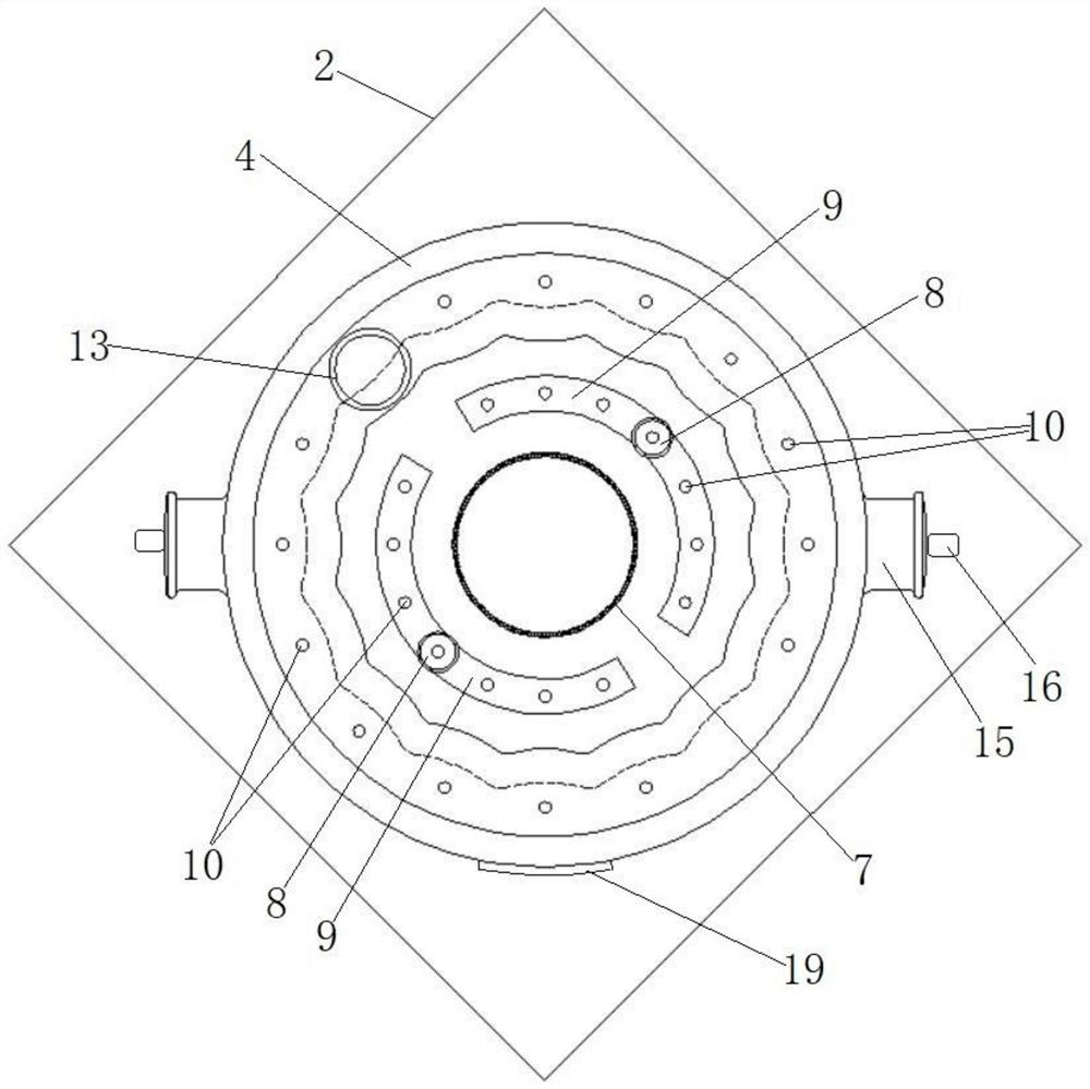
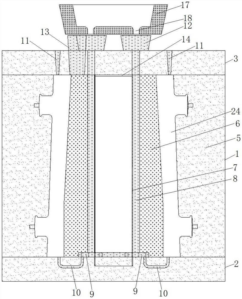
[0047] Such as Figure 1 ~ Figure 3 As shown, a modeling structure for making a large-scale floating steel ingot mould, including a bottom box 2, a middle box 1 and a cover box 3 stacked in sequence, the middle box 1 is provided with a solid foam model 4, and the solid foam model 4 Sand molds 5 are filled between the foam model 4 and the middle box 1, and the outer periphery of the solid foam model 4 is provided with several pairs of trunnion models 15, and the trunnion models 15 are provided with positioning core heads 16, and the positioning One end of the core head 16 is inserted in the sand mold 5, and the outer wall of the solid foam model 4 is also provided with a casting model, and the casting model is provided with a boss movable block 19; the inner peripheral part of the solid foam model 4 A sand core 6 is provided, and a core barrel 7 is provided in the middle of the sand core 6. A pair of sprues 8 are symmetrically arranged in the sand core 6 near the core barrel 7,...

Embodiment 2

[0067] This embodiment provides the casting method of the steel ingot mold in the first embodiment.

[0068] combine Figure 1 to Figure 8 Shown, a kind of casting method that is used to make large floating type steel ingot mould, comprises the steps:

[0069] (1) Foam pattern production: add 0.6% scale on the basis of the part drawing, add 20mm machining allowance, make a three-dimensional map of the foam model, and divide it into upper and lower parts according to the structural characteristics, that is, the floating straight part 402 and the floating part Divide the upper and lower parts into 8 equal parts in the circumferential direction; the 8 equal parts of the floating straight part are cut and formed by digital milling with a 1:1 size, and assembled after cutting to complete the floating straight part Model; the outer wall of the 8 equal parts of the module in the floating inclined section is cut and formed by digital milling at a 1:1 size, and the inner wall is reser...


PUM

PropertyMeasurementUnit
Sizeaaaaaaaaaa

Abstract

The invention discloses a modeling structure and a casting method for manufacturing a large floating type ingot mold. A foam solid model is adopted, a boss loose piece is arranged at a typecasting position of the model, round steel positioning core head loose pieces are arranged outside trunnion models, a waste cast pipe is used for manufacturing core iron, an outer cavity of the foam solid model is wrapped with a layer of thin iron sheet, a bottom shower in-core pouring system is arranged, a quantitative pouring pool corresponds to two sprue cups to achieve simultaneous pouring of double ladles, a 1: 1 clamping plate is self-made to detect a sand core, quantitative box pressing iron and a sand box outer wall are fastened through bolts for double insurance, and the heat preservation time of a casting in a sand mold is controlled to be 72 hours or above; a resin sand foam model buckle mold casting process is adopted, a foam mold is used for replacing a traditional wood mold for modeling and core manufacturing, and the manufacturing period and the manufacturing cost of the model are greatly saved; the bottom shower in-core pouring system is stable in mold filling, a cavity is not directly impacted, and the problem that bumps on the inner wall of the ingot mold are not easy to clean is solved; and the sand-iron ratio is greatly reduced, and the production cost is greatly reduced.

Description

technical field [0001] The invention relates to the technical field of large steel ingot mold casting, in particular to a modeling structure and casting method for making large floating steel ingot molds. Background technique [0002] The wall thickness of large floating steel ingot mold castings is as high as 280-360mm, the height is 3000-4200mm, and the unit weight is more than 32t. Traditional casting uses wooden core boxes and steel plate tailor-welded outer molds. After molding, core making, and assembly, casting is formed. The mold production cycle is long, the cost is high, and the production efficiency is low and cannot meet the delivery requirements. The traditional casting adopts the bottom injection stepped gating system. The bulging of the inner wall of the ingot mold caused by the direct flushing of the core by the inner runner is not easy to clean and smooth, and the gating system is distributed on the outside of the ingot mold. The sand and iron ratio of the i...

Claims


Application Information

Patent Timeline
IPC IPC(8): B22C9/04B22C9/08B22C9/22B22D7/06
CPCB22C9/04B22C9/22B22C9/082B22C9/088B22D7/066Y02P10/20
Inventor 雷翠平
Owner 黄石新兴管业有限公司
Why Eureka
Try Eureka