Backflow-prevention and smell-resistance hydraulic self-control valve device and application method

A hydraulic self-control and anti-backflow technology, applied in the direction of valve device, valve operation/release device, safety device, etc., can solve the problems of drainage system with many electrical equipment, complicated maintenance and management, and high maintenance cost

Pending Publication Date: 2017-11-10
TIANJIN BRITISH IRON TECH CO LTD
View PDF0 Cites 0 Cited by
  • Summary
  • Abstract
  • Description
  • Claims
  • Application Information

AI Technical Summary

Problems solved by technology

Therefore, the investment in construction facilities is large, the area is large, the electrical equipment of the drainage system is large, the maintenance management is complicated, and the maintenance cost is high.

Method used


Image

  • Backflow-prevention and smell-resistance hydraulic self-control valve device and application method
  • Backflow-prevention and smell-resistance hydraulic self-control valve device and application method
  • Backflow-prevention and smell-resistance hydraulic self-control valve device and application method

Examples


Embodiment Construction

[0020] Below according to accompanying drawing and embodiment the present invention will be described in further detail:

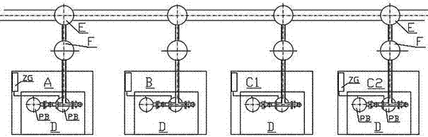
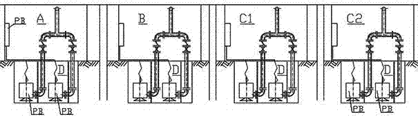
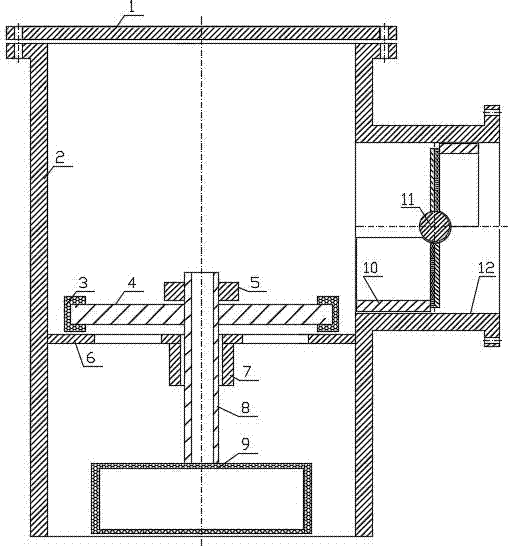
[0021] An anti-backflow and odor-resistant hydraulic self-control valve device, comprising an air shaft main body, a valve body Z, and a communication pipe L. The side wall of the communication pipe L has a pipe interface K, and the pipe interface K is connected to the valve body Z. The valve body Z is a three-way pipe, and the side wall of the vertical pipe 2 has a horizontal pipe 12, and the vertical pipe 2 communicates with the horizontal pipe 12. The inside of the vertical pipe 2 has a cross ring plate 6, and the height of the cross ring plate 6 is lower than that of the horizontal pipe. 12 height, the middle part of the cross ring plate 6 is a cross shape, the lower part of the cross ring plate 6 is connected to the limit pipe 7, the upper part of the cross ring plate 6 is connected to the disc 4, and the outer side of the disc 4 is connected to the se...


PUM


Abstract

The anti-backflow and odor hydraulic automatic control valve device and its use method, the anti-backflow and odor hydraulic automatic control valve device, including the main body of the air shaft, the valve body, and the connecting pipe. The side wall of the connecting pipe has a pipe interface, and the pipe interface is connected to the valve body. The valve body is in the shape of a three-way pipe, the side wall of the standpipe has a horizontal pipe, the standpipe communicates with the horizontal pipe, the inside of the standpipe has a cross ring plate, and the height of the cross ring plate is lower than that of the horizontal pipe. The middle part of the cross ring plate is cross-shaped, the lower part of the cross ring plate is connected to the limit pipe, the upper part of the cross ring plate is connected to the disc assembly plate, the outer side of the plate assembly plate is connected to the sealing ring, and the bottom of the sealing ring is connected to the cross ring plate, The middle part of the disc is connected to the connecting rod through a nut, and the connecting rod passes through the cross ring plate and the limit tube. The bottom of the connecting rod is connected to the buoyancy tank. A gravity door is arranged on the top, the top of the vertical pipe is connected with a blocking cover, and the nozzle at the bottom of the vertical pipe is open.

Description

technical field [0001] The invention relates to the technical field of environmental control and connected drainage of a tunnel air shaft group, in particular to an anti-backflow and odor hydraulic automatic control valve device and a use method thereof. Background technique [0002] In terms of comprehensive drainage of the fluid system, such as the discharge of sewage and gas sewage, the current drainage system only has water-sealed wells, and water-sealed wells may sometimes be closed without water, resulting in the risk of gas sewage spreading along the pipeline. In the intensive setting of subway tunnel air well management, the existing air well group sump is equipped with an independent drainage pump system such as figure 1 , 2 As shown, air shaft groups are set at both ends of the station, and each group is respectively equipped with a fresh air shaft A, a row of air shafts B, the first piston air shaft C1, and the second piston air shaft C2. In the area, each win...

Claims


Application Information

Patent Timeline
Patent Type & Authority Applications(China)
IPC IPC(8): F16K1/00F16K31/22F16K1/18E21F16/02
CPCF16K1/00E21F16/02F16K1/18F16K31/22
Inventor 贺占民
Owner TIANJIN BRITISH IRON TECH CO LTD
Why Eureka
Try Eureka