Burner
A burner, gas technology, applied in the direction of burner, burner, burner cooling, etc., can solve the problems of easy fire breakage, ignition difficulty, etc., to avoid fire breakage, reduce high temperature radiation and erosion wear, excellent wear resistance and the effect of high temperature resistance
- Summary
- Abstract
- Description
- Claims
- Application Information
AI Technical Summary
Problems solved by technology
Method used
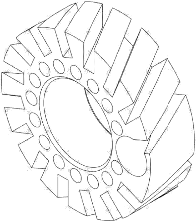
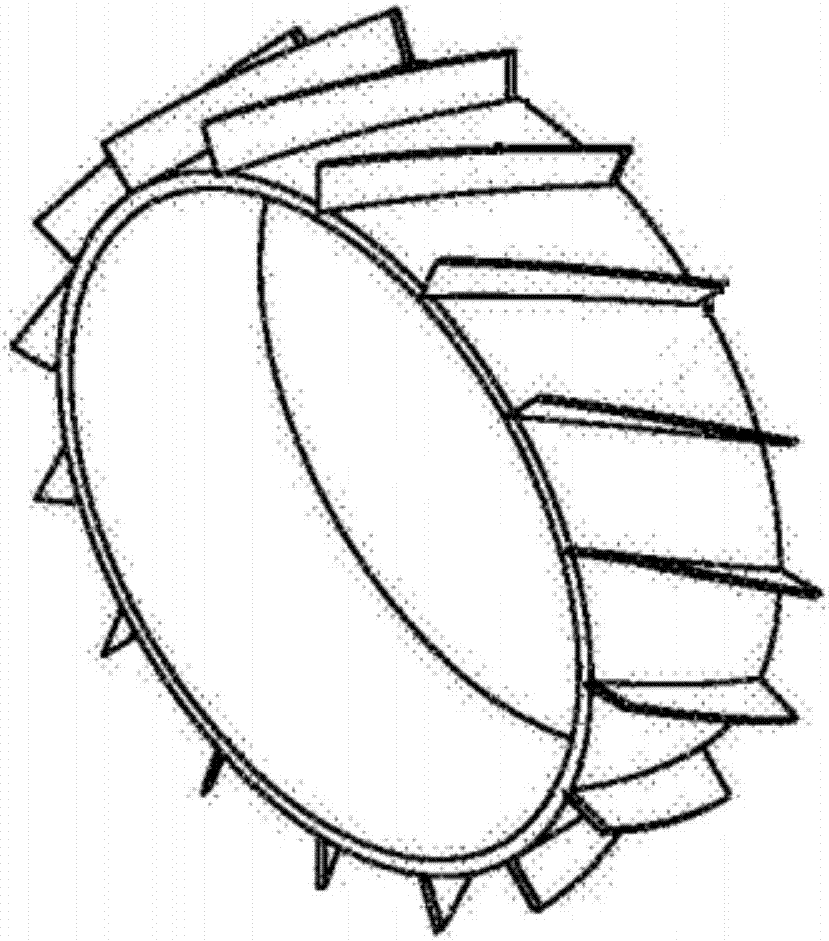
Image

Examples
Embodiment 1
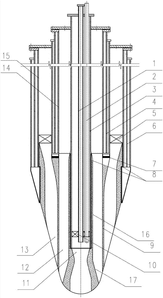
[0051] like figure 1 As shown, a burner includes a rear section steel assembly and a front section integral ceramic prefabricated part 9 ', and the front section integral ceramic prefabricated part 9 is fixedly arranged at the front end of the rear section steel assembly;
[0052] The rear section steel components include:
[0053] A gas casing 1, the gas casing 1 has a gas channel;
[0054] An air sleeve 3, the air sleeve 3 is sleeved on the outside of the gas sleeve 1, and an air channel is defined between the inner wall of the air sleeve 3 and the outer wall of the gas sleeve 1;
[0055] Pulverized coal casing 14, the pulverized coal casing 14 is sleeved on the outside of the air casing 3, and the rear section of the casting is defined between the inner wall of the pulverized coal casing 14 and the outer wall of the air casing 3. powder channel;
[0056] Gasification agent sleeve 15, the gasification agent sleeve 15 is sleeved on the outside of the pulverized coal sleeve...
Embodiment 2
[0066] like figure 1 Shown, a kind of burner, its structure is compared with embodiment 1, the difference is: the inner surface of described flame holding section 17 transitions smoothly, and the inner diameter of its outlet end is equal to the inner diameter of said air sleeve 3 , which ensures that the jetted flame has high rigidity and is not easy to be blown out by coal powder and gasification agent.
Embodiment 3
[0068] like figure 1 As shown, a kind of burner, its structure is compared with embodiment 1, the difference is that: the gasifying agent channel 13 in the front stage is a structure that shrinks first and then expands from the inlet to the outlet, which increases the gasifying agent injection velocity, Promote the mixing and atomization of gasification agent and coal powder.
PUM
 Abstract
Description
Claims
Application Information
 - R&D
- Intellectual Property
- Life Sciences
- Materials
- Tech Scout
- Unparalleled Data Quality
- Higher Quality Content
- 60% Fewer Hallucinations
Browse by: Latest US Patents, China's latest patents, Technical Efficacy Thesaurus, Application Domain, Technology Topic, Popular Technical Reports.
© 2025 PatSnap. All rights reserved.Legal|Privacy policy|Modern Slavery Act Transparency Statement|Sitemap|About US| Contact US: help@patsnap.com