
Organic light-emitting display panel, preparation method, and organic light-emitting display device

A light-emitting display, organic technology, used in semiconductor/solid-state device manufacturing, semiconductor devices, electrical components, etc., can solve the adhesive stress mismatch, the adhesive is prone to cracks, and the water and/or oxygen barrier of organic light-emitting display panels Poor performance and other problems, to achieve the effect of improving production yield and avoiding disconnection

Active Publication Date: 2017-11-10
WUHAN TIANMA MICRO ELECTRONICS CO LTD
View PDF4 Cites 11 Cited by
  • Summary
  • Abstract
  • Description
  • Claims
  • Application Information

AI Technical Summary

Problems solved by technology

When the adhesive is heated and melted by lasers such as infrared rays, the adhesive will not only adhere to the surface of the reflective layer, but also usually adhere to the inorganic material layer or the fan-out wire exposed by the bonding hole, thereby The stress mismatch between the inside and outside of the bonding hole will cause the adhesive to have defects such as cracks after melting, and the water and / or oxygen barrier performance of the organic light-emitting display panel is poor, which reduces the production quality of the organic light-emitting display panel. Rate

Method used


Image

  • Organic light-emitting display panel, preparation method, and organic light-emitting display device
  • Organic light-emitting display panel, preparation method, and organic light-emitting display device
  • Organic light-emitting display panel, preparation method, and organic light-emitting display device

Examples


Embodiment Construction

[0022] The principles and features of the present application will be further described in detail below in conjunction with the drawings and embodiments. It should be understood that the specific embodiments described here are only used to explain related inventions, rather than to limit the invention. It should also be noted that, for ease of description, only parts related to the invention are shown in the drawings.

[0023] It should be noted that, in the case of no conflict, the embodiments in the present application and the features in the embodiments can be combined with each other. The present application will be described in detail below with reference to the accompanying drawings and embodiments.

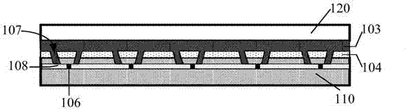
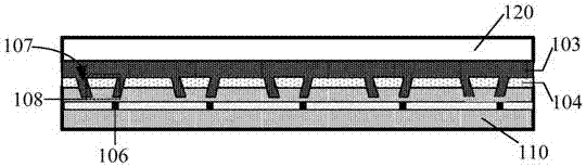
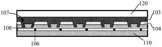
[0024] Please refer to figure 1 and 2 ,in, figure 1 shows a schematic structural view of an embodiment of an organic light emitting display panel according to the present application, figure 2 show figure 1 An enlarged view of the local structure of the organic light...


PUM


Abstract

The invention discloses an organic light-emitting display panel, a preparation method, and an organic light-emitting display device. The organic light-emitting display panel comprises an array substrate which comprises a display region and a non-display region surrounding the display region; a reflection layer which is disposed in the non-display region of the array substrate, surrounds the display region, and is provided with a plurality of binding holes; stress releasing structures which are respectively disposed in all bonding holes; a cover plate which is arranged to be opposite to the array substrate; and a binding agent which is disposed between the array substrate and the cover plate, and is used for packaging the array substrate and the cover plate. The binding agent is disposed at gaps between the stress releasing structures and the binding holes, and the stress releasing structures are used for releasing the stress generated during the binding of the binding agent with the binding holes. The array substrate also comprises a plurality of fan-out lead wires which are electrically connected with a drive chip. The stress releasing structures can release the stress in the binding holes, thereby protecting the binding agent from cracking, and improving the production yield of the organic light-emitting display panel.

Description

technical field [0001] The present application generally relates to the field of display technology, in particular to the field of organic light-emitting display technology, and specifically relates to an organic light-emitting display panel, a manufacturing method, and an organic light-emitting display device including the organic light-emitting display panel. Background technique [0002] OLED, that is, Organic Light-Emitting Diode (Organic Light-Emitting Diode), also known as organic electroluminescent device, its light-emitting principle is mainly: organic semiconductor materials and light-emitting materials are driven by an electric field through carrier injection and recombination. glow. Organic electroluminescent devices have many advantages such as self-luminescence, high efficiency, low voltage, fast response, wide viewing angle, and can be made on flexible substrates. They can be made into displays or lighting devices, and have attracted much attention from the soc...

Claims


Application Information

Patent Timeline
IPC IPC(8): H01L27/32H01L51/52H01L51/56
CPCH10K59/12H10K59/131H10K50/8426H10K71/00
Inventor 李玉军
Owner WUHAN TIANMA MICRO ELECTRONICS CO LTD
Features
  • Generate Ideas
  • Intellectual Property
  • Life Sciences
  • Materials
  • Tech Scout
  • Unparalleled Data Quality
  • Higher Quality Content
  • 60% Fewer Hallucinations
Learn More