
Artificial prosthesis of long bone diaphysis tenon and mortise structure

A technology of artificial prosthesis and skeleton, which is applied in the direction of skull, femur, bone implant, etc., can solve problems such as the influence of the service life of the limb, the complicated and complicated operation of joint reduction, and the difficulty in grasping the concentricity of the connecting part, so as to achieve a long service life. , Revision surgery is easy, and the effect of making up for the poor initial stability

Pending Publication Date: 2017-11-17
胡永成
View PDF8 Cites 6 Cited by
  • Summary
  • Abstract
  • Description
  • Claims
  • Application Information

AI Technical Summary

Problems solved by technology

In cases of bone defects in the long bone of limbs caused by severe trauma, infection, etc., it is also necessary to remove too many normal bones and even joints in order to place huge prostheses, although this can solve the immediate problem , but the function of the limb and the service life of the prosthesis must be greatly affected by the removal of too many bones or joints
[0008] In addition, the overlapping connection structure is adopted, and the repositioning operation during the operation often requires repeated alignment, and after the alignment is successful, it needs to be held for a long time to prevent the connection between the proximal and distal handles of the prosthesis from shifting and falling out until the final screwing. Two screws were inserted to fix and lock the distal and proximal handles of the prosthesis, which made it difficult to grasp the concentricity of the two connecting parts, and the operation of inversion and reduction during the operation was cumbersome and complicated

Method used


Image

  • Artificial prosthesis of long bone diaphysis tenon and mortise structure
  • Artificial prosthesis of long bone diaphysis tenon and mortise structure
  • Artificial prosthesis of long bone diaphysis tenon and mortise structure

Examples


Embodiment Construction

[0032] In order to enable those skilled in the art to better understand the technical solution of the present invention, the specific embodiments of the present invention will be further described below in conjunction with the accompanying drawings:

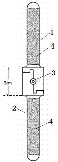
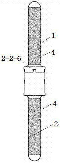
[0033] like Figure 1 to Figure 8 As shown, an artificial prosthesis with a mortise-and-tenon structure of a long bone stem includes a proximal stem 1 , a distal stem 2 , and a tenon 3 .

[0034] The handle I1-1 of the proximal handle 1 of the prosthesis and the handle II2-1 of the distal handle 2 are both cylindrical, and the tail end I1-3 of the proximal handle 1 of the prosthesis and the tail end II2- 3 are hemispheres.

[0035] A layer of rough metal coating 4 is provided on the surfaces of handle I1-1 and handle II2-1.

[0036] The connecting part I1-2 of the proximal handle 1 of the prosthesis and the connecting part II2-2 of the distal handle 2 are mirror symmetrical structures, both of which are irregular shapes compose...


PUM


Abstract

The invention relates to an artificial prosthesis of a long bone diaphysis tenon and mortise structure. A protruding face I and a rectangular protrusion I of a prosthesis proximal handle connecting part I are inserted into a strip-shaped groove II and a rectangular notch II of a prosthesis far-end handle connecting part II respectively, a protruding face II and a rectangular protrusion II of the prosthesis far-end handle connecting part are inserted into a strip-shaped groove I and a rectangular notch I of the prosthesis proximal handle connecting part I respectively, after a semicircular groove I of the prosthesis proximal handle connecting part I is in butt joint with a semicircular groove II of the prosthesis far-end handle connecting part II, a cylindrical counter bore is formed, tenon is inserted into the cylindrical counter bore formed in one end of the cylinder, and the tenon locks the connecting part I and the connecting part II together. Prosthesis fixation is firm and reliable, the operation is simple and convenient, the operation time is shortened, the operation effect and efficiency are improved, and operative complications are reduced. The artificial prosthesis can be widely applied to different defects of long bone diaphysis, the minimum osteotomy amount can reach 3.0 cm, and the maximum opportunity is provided for reserving normal bone tissue and joints as much as possible.

Description

technical field [0001] The invention relates to an artificial prosthesis with a mortise-and-tenon structure of the shank of a long bone, which is suitable for the technical field of reconstruction of a bone shank defect in the clinic, and specifically relates to the long bones of the limbs including humerus, ulna, radius, femur, tibia, and fibula. The backbone artificial prosthesis for the reconstruction of structural bone defects caused by osteotomy operations such as primary or metastatic tumor resection for limb salvage, severe post-traumatic bone defects, and severe infected osteomyelitis. Background technique [0002] With the development of surgical diagnosis and treatment technology, the innovation of imaging technology and the wide application of perioperative neoadjuvant chemotherapy technology, limb salvage and joint preservation surgery has become the main trend and direction of bone tumor treatment; at the same time, severe trauma, infection Structural bone defec...

Claims


Application Information

Patent Timeline
Patent Type & Authority Applications(China)
IPC IPC(8): A61F2/28
CPCA61F2/28A61F2002/2853A61F2002/2825A61F2002/2896A61F2002/2892A61F2002/2871
Inventor 胡永成张剑锋田东牧王磊
Owner 胡永成
Learn More