A cavity system with high uniformity and low temperature coefficient

A technology with low temperature coefficient and uniformity, applied in electrical components, automatic control of power, output stability, etc., can solve the problems of high temperature coefficient of microwave cavity, difficult repeated processing, difficult surface polishing, etc., to improve the signal-to-noise ratio , Improve the filling factor and direction factor, and the effect of axial magnetic field uniformity

Inactive Publication Date: 2021-10-22
NAT TIME SERVICE CENT CHINESE ACAD OF SCI
View PDF7 Cites 0 Cited by
  • Summary
  • Abstract
  • Description
  • Claims
  • Application Information

AI Technical Summary

Problems solved by technology

Magnetron microwave cavity [A Kind of magnetron cavity used in rubidium atomic frequency standards, Yang Shuiyu, Cuijingzhong, TuJianhui, and Liang Yaoting, Journal of Semiconductors, Vol.32, No.12, 2011; Compact microwave cavity for high performance rubidium frequency standard ,C.Stefanucci and G.Mileti,Review of Scientific Instruments 83,104706,2012]: The cavity of the microwave cavity is processed in one time, and has excellent mechanical stability, but the processing accuracy is high, and the surface polishing is difficult. The cost of obtaining a high Q value is high. The Q value of the same cavity is between 500-1000, and the volume of the bubble is small. The filling factor of the microwave cavity is half that of the TE011 mode.
The common point of the above types of cavities is that the temperature coefficient of the microwave cavity is relatively large. Although the temperature coefficient of the microwave cavity can be reduced by filling the inside of the microwave cavity with a medium, it is difficult to repeat the process.

Method used


Image

  • A cavity system with high uniformity and low temperature coefficient
  • A cavity system with high uniformity and low temperature coefficient
  • A cavity system with high uniformity and low temperature coefficient

Examples


Embodiment 1

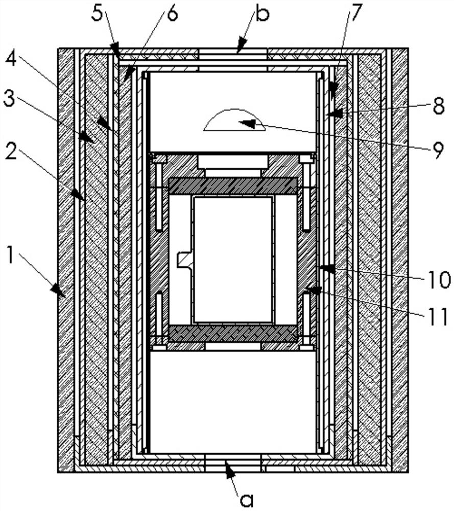
[0033] exist figure 1 Among them, the present invention is a cavity system with high uniformity and low temperature coefficient. The system consists of outer thermal insulation layer 1, outer magnetic shielding cylinder 2, middle thermal insulation layer 3, outer heating cylinder 4, middle Magnetic shielding cylinder 5, inner thermal insulation layer 6, inner heating cylinder 7, inner magnetic shielding cylinder 8, detector 9, C field coil 10, microwave resonant cavity 11. The thermal insulation layer is polyurethane or thermal insulation material coated with reflective tin film, which is wrapped on the outside of the heating layer to insulate the physical system; the heating cylinder is an aluminum cylinder with twisted twisted The resistance heating wire heats the entire physical system by controlling the current of the heating wire, and the residual magnetic field generated by the heating current can be eliminated as much as possible by using a twisted pair; the C field coi...


PUM

PropertyMeasurementUnit
thicknessaaaaaaaaaa
pore sizeaaaaaaaaaa

Abstract

A cavity bubble system with high uniformity and low temperature coefficient, comprising an outer thermal insulation layer, an outer magnetic shielding cylinder, a middle thermal insulation layer, an outer heating cylinder, a middle magnetic shielding cylinder, an inner thermal insulation layer, an inner heating cylinder, an inner Magnetic shielding cylinder, C field coil, and microwave resonant cavity. Both ends of the system are equipped with incident and outgoing light holes; the rubidium bubble is filled with a suitable proportion of buffer gas to reduce the influence of temperature fluctuations; a new type of microwave cavity, microwave cavity There are rubidium bubbles and two dielectric discs inside. Compared with the TE011 mode, the axial magnetic field uniformity is high, and the influence of the axial dimension on the resonance frequency is greatly reduced, thus reducing the influence of temperature on the cavity frequency; the microwave cavity The front and rear end covers can be equipped with polarizers and focusing lenses, and can be used for light detection or polarized light detection of atomic clocks by coating different dielectric plates; the cavity bubble system has high axial magnetic field uniformity, low temperature coefficient, cavity Q value High characteristics can improve the short-term and medium-term and long-term stability of the rubidium atomic clock.

Description

technical field [0001] The invention belongs to the technical field of atomic frequency standards, and in particular relates to a cavity bubble system with high uniformity and low temperature coefficient. Background technique [0002] Atomic frequency standard (also known as atomic clock) is a device that provides standard frequency and time. Rubidium atomic clock has become the most widely used atomic frequency standard because of its small size, light weight and low power consumption. The rubidium atomic frequency standard can be roughly divided into the circuit part and the physical part. The physical part is the core device of the whole machine, and its performance determines the frequency stability of the rubidium atomic frequency standard. [0003] The rubidium atomic frequency standard adopts the ground state hyperfine energy level (F=2,m F =0→F=1,m F =0) as the clock transition frequency, where the microwave cavity is the place where the microwave field interacts w...

Claims


Application Information

Patent Timeline
Patent Type & Authority Patents(China)
IPC IPC(8): H03L1/04H03L7/26
CPCH03L1/04H03L7/26
Inventor 杜志静王柯穆鱼志健张首刚薛文祥
Owner NAT TIME SERVICE CENT CHINESE ACAD OF SCI
Why Eureka
Try Eureka