Magnetic induced shrinkage or elongation touch sensor array for intelligent manipulator

A technology of tactile sensors and intelligent manipulators, applied in the field of sensor arrays, can solve the problems of difficulty in making sensor arrays and low test accuracy, and achieve the effects of uniform axial magnetic field, increased sensitivity, and improved measurement accuracy

Pending Publication Date: 2019-03-08
HEBEI UNIV OF TECH
View PDF0 Cites 6 Cited by
  • Summary
  • Abstract
  • Description
  • Claims
  • Application Information

AI Technical Summary

Problems solved by technology

[0003] Aiming at the problems of low test accuracy and difficulty in making sensor arrays in tactile sensors, the present invention designs a new type of magnetostrictive tactile sensor array in order to realize accurate measurement and identification of tactile force by intelligent manipulators

Method used


Image

  • Magnetic induced shrinkage or elongation touch sensor array for intelligent manipulator
  • Magnetic induced shrinkage or elongation touch sensor array for intelligent manipulator
  • Magnetic induced shrinkage or elongation touch sensor array for intelligent manipulator

Examples


Embodiment 1

[0047] Example 1: The relationship between the applied force and the output voltage of a FeGa wire with a length of 16mm and a diameter of 0.8mm in the range of 0-2N. The main purpose of this embodiment is to study the input-output relationship, sensitivity and linearity of the sensor array.

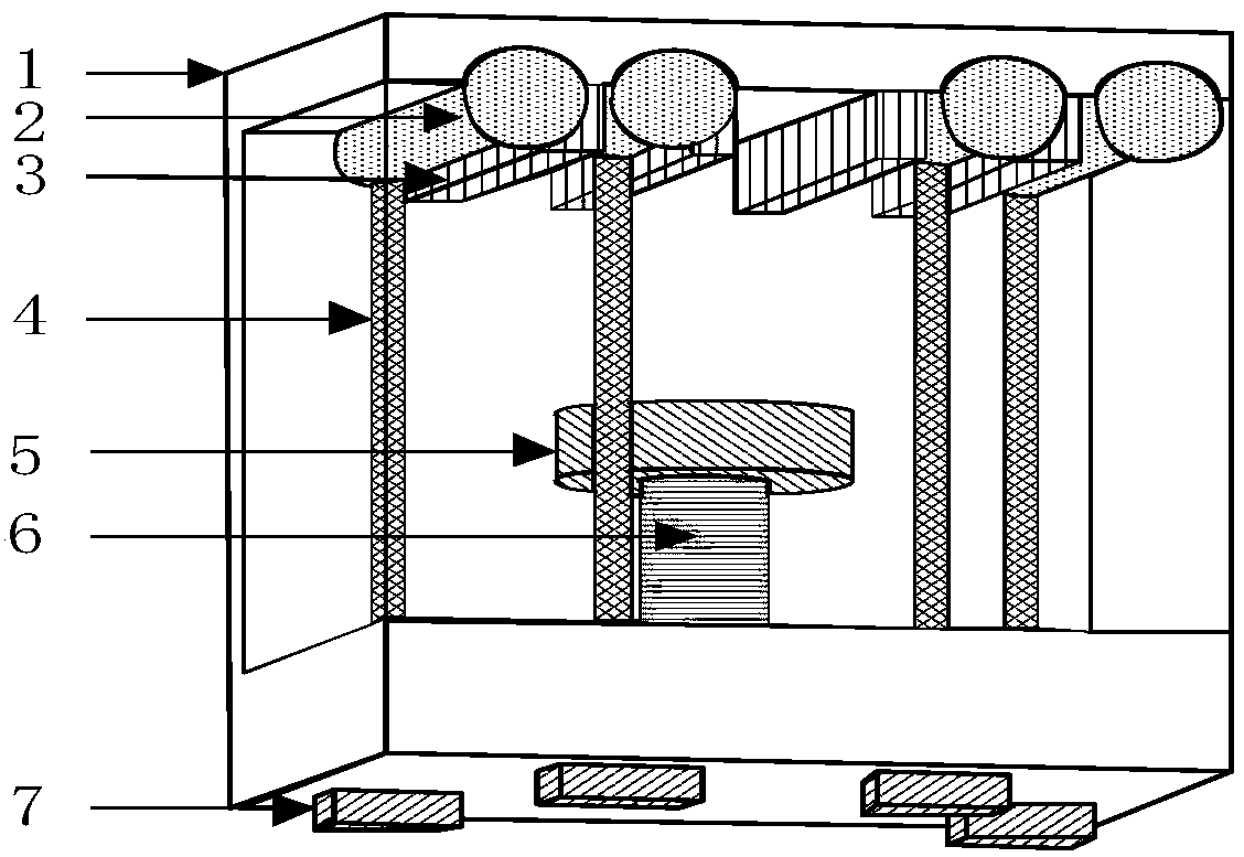
[0048] Experimental platform construction: according to figure 1 The sensor array structure shown is installed with various components, and the installed sensor array is fixed on the test bench. The vertical pressure applying device and the linear motor are respectively used to provide the known static force and dynamic force signals for the sensor. The output voltage signal of the Hall element is determined by The DH-8303 data acquisition card collects and transmits to the computer for display.

[0049] The software or protocols involved in the present invention are all known technologies.

[0050] Experimental process and results: Connect the output terminals of the sensor array to ...

Embodiment 2

[0051] Embodiment 2: A linear motor is used to apply a dynamic pressure, simulating the pressure when the hand grabs an object, and testing the dynamic output characteristics of the magnetostrictive tactile sensor array. The experimental platform is composed of signal generator, power amplifier, linear motor, DC regulated power supply, data acquisition card and PC computer. During the experiment, the output terminals of the sensor array were connected to the data acquisition card, and the acquisition card was connected to the computer, and the test data was read by the computer. A signal generator, a power amplifier and a linear motor are connected to provide sinusoidally varying forces with different frequencies and amplitudes. The DC regulated power supply is connected to the Hall element to provide a stable voltage for it.

[0052] The relationship between the output voltage and time of the sensor array obtained when the pressure amplitude is 1N and the frequency is 2Hz is...


PUM

PropertyMeasurementUnit
Diameteraaaaaaaaaa
Diameteraaaaaaaaaa
The inside diameter ofaaaaaaaaaa

Abstract

The invention relates to a magnetic induced shrinkage or elongation touch sensor array for an intelligent manipulator. The sensor array comprises a sensor array casing, a circular-ring-shaped permanent magnet, a cylindrical pedestal, and four magnetic induced shrinkage or elongation sensing units; an FeGa wire is distributed vertical, and the lower end of the FeGa wire penetrates the bottom of thecasing and makes contact with Hall elements in the bottom of the casing; the upper end of the FeGa wire is connected with a horizontal transmission rod with a contact; the Hall elements are positioned in four vertexes of an isosceles trapezoid, the lower bottom of the isosceles trapezoid is positioned in a position close to the back wall of the bottom of the casing, and distances from two top points of the upper side to the central point of the lower bottom of the isosceles trapezoid both equal half of the length of the lower bottom; and the cylindrical pedestal is fixed on the middle point of the lower bottom of the isosceles trapezoid, and the circular-ring-shaped permanent magnet is fixed in the top end of the cylindrical pedestal. Thus, the touch force measuring precision of the intelligent manipulator can be met.

Description

technical field [0001] The invention applies the magnetostrictive FeGa material to the field of sensor arrays of intelligent manipulators, and mainly relates to a novel magnetostrictive tactile sensor array based on FaGa filamentary materials, which can be applied to the end of a mechanical finger to realize precise perception of touch. The core part of the tactile sensor array is a magnetostrictive filamentary material, and contains a ring-shaped permanent magnet, a transmission rod with contacts, a shell, and a Hall element. It is characterized by simple structure, small size, fast response and good stability. According to the advantages of small volume of FeGa filament material, a multi-contact sensor array is designed and installed on the intelligent manipulator. technical background [0002] With the continuous development of modern industrialization, intelligent manipulators are widely used in industry, and the requirements for the accuracy of intelligent manipulators...

Claims


Application Information

Patent Timeline
IPC IPC(8): G01L1/12
CPCG01L1/125
Inventor 王博文张冰王亮翁玲薛丰李明明
Owner HEBEI UNIV OF TECH
Why Eureka
Try Eureka