
Thread dismounting device applicable to oil pressure vibration reducer

A technology for hydraulic shock absorbers and dismantling devices, which is applied in metal processing, metal processing equipment, manufacturing tools, etc., and can solve problems such as the inability to meet batch inspections of hydraulic shock absorbers, heavy maintenance tasks, and high work intensity. Achieve the effect of convenient disassembly, improving work quality and reducing labor intensity

Pending Publication Date: 2017-11-17
ZHUZHOU LINCE GRP +1
View PDF4 Cites 4 Cited by
  • Summary
  • Abstract
  • Description
  • Claims
  • Application Information

AI Technical Summary

Problems solved by technology

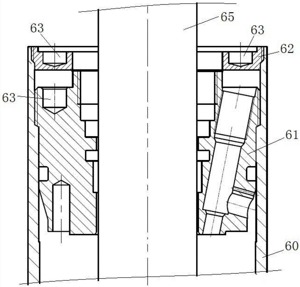
The oil pressure shock absorber of rolling stock is a vulnerable part, which requires regular maintenance of the shock absorber, and the maintenance task is also very large. (For the specific structure of the outer screw cover and the guide, please refer to figure 1 ), in order to ensure good fastening performance, thread fastening glue is used for the thread between the outer screw cover and the cylinder body of most oil pressure shock absorbers and the thread between the guide and the cylinder body, so that the ordinary disassembly method has the advantages of Certain difficulty, the existing disassembly method generally uses heating, baking and other methods to destroy the thread fastening glue, and then manually disassembles it on the vise with a wrench. The operation is cumbersome, the work intensity is high, and the efficiency is low. Compression damper requirements

Method used


Image

  • Thread dismounting device applicable to oil pressure vibration reducer
  • Thread dismounting device applicable to oil pressure vibration reducer
  • Thread dismounting device applicable to oil pressure vibration reducer

Examples


Embodiment Construction

[0035]The embodiments of the present invention will be described in detail below with reference to the accompanying drawings, but the present invention can be implemented in various ways defined and covered by the claims.

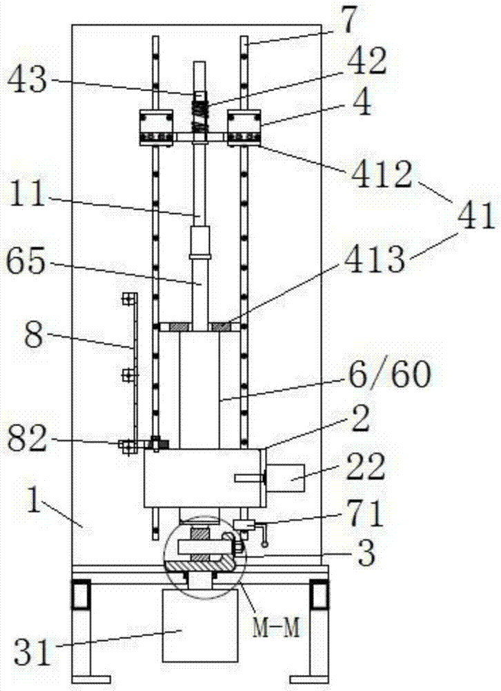
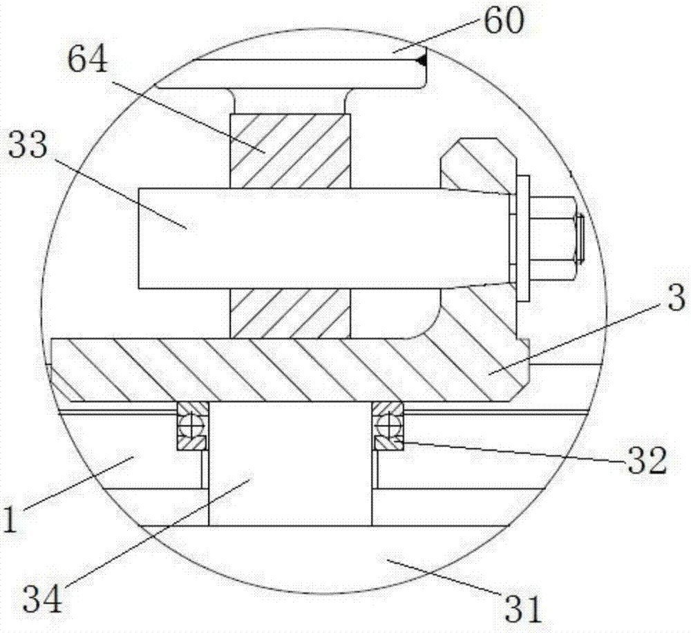
[0036] See Figure 2 (including Figure 2a and Figure 2b )~ Figure 12 The hydraulic shock absorber thread removal device includes a frame 1 and a centering clamping mechanism 2, a turret 3 and a wrench assembly 4 respectively arranged on the frame, and the centering clamping mechanism is arranged between the turret and the wrench assembly. In this embodiment, the wrench assembly is arranged above the centering clamping mechanism, and the turret is arranged below the centering clamping mechanism, and the centering clamping mechanism is used for positioning and clamping the cylinder body 60 of the hydraulic shock absorber to be disassembled. And make the axis line of the cylinder body coincide with the positioning center line of the centering clamping mech...


PUM


Abstract

The invention provides a thread dismounting device applicable to an oil pressure vibration reducer. The device comprises a frame (1), and a centering clamping mechanism (2), a rotating frame (3) and a spanner module (4) respectively arranged on the frame; the centering clamping mechanism can enable the oil pressure vibration reducer to be dismounted to rotate during being positioned and clamped; the rotating frame (3) is rotationally arranged on the frame (1), and the rotating axis line of the rotating frame is overlapped with the positioning center line of the centering clamping mechanism; the spanner module (4) comprises a clamping pressure plate (41) and an elastic part (42); a positioning key (410) for preventing rotation of a guide bearing or an external screw cover in the dismounting process is arranged at the bottom of the clamping pressure plate; and the elastic part (42) is used for compensating the retreating displacement of the guide bearing or the external screw cover. The device can realize quick dismounting of the guide bearing or the external screw cover, is strong in power, needs no preheating and baking to damage fastening glue, relives the labor intensity, and improves the working efficiency and quality.

Description

technical field [0001] The invention relates to maintenance equipment for oil pressure shock absorbers, in particular to a thread removal device for oil pressure shock absorbers. Background technique [0002] With the leapfrog development of railways, the demand for rolling stock is increasing day by day, and the demand for hydraulic shock absorbers, an important component used to attenuate the vibration of rolling stock, is increasing. The oil pressure shock absorber of rolling stock is a vulnerable part, which requires regular maintenance of the shock absorber, and the maintenance task is also very large. (For the specific structure of the outer screw cover and the guide, please refer to figure 1 ), in order to ensure good fastening performance, thread fastening glue is used for the thread between the outer screw cover and the cylinder body of most oil pressure shock absorbers and the thread between the guide and the cylinder body, so that the ordinary disassembly method ...

Claims


Application Information

Patent Timeline
IPC IPC(8): B23P19/04
CPCB23P19/04Y02W30/56
Inventor 陈湘廖学官樊友权戴谋军王三槐
Owner ZHUZHOU LINCE GRP
Learn More