Main brush structure of sweeping machine

A sweeper and main brush technology, applied in road cleaning, construction, cleaning methods, etc., can solve the problems of wasting labor, time-consuming, and tedious replacement of the main brush, and achieve the effect of reducing disassembly steps, saving steps, and saving time.

Pending Publication Date: 2017-11-17
NANTONG MINGNUO ELECTRIC TECH CO LTD
View PDF5 Cites 1 Cited by
  • Summary
  • Abstract
  • Description
  • Claims
  • Application Information

AI Technical Summary

Problems solved by technology

The main brush of the sweeper is a consumable part. Generally, it needs to be replaced after about three months of cleaning. At present, the replacement of the main brush of the sweeper on the market is cumbersome, time-consuming and labor-intensive. In order to solve this technical problem, a main brush is invented. replacement structure

Method used


Image

  • Main brush structure of sweeping machine
  • Main brush structure of sweeping machine
  • Main brush structure of sweeping machine

Examples


Embodiment Construction

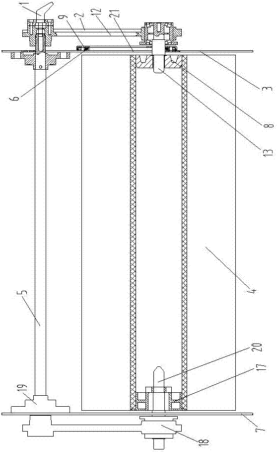
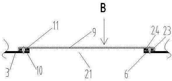
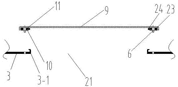
[0020] Such as figure 1 As shown in -7, the main brush structure of the sweeper includes a left side plate 3, a right side plate 7, a main brush 4 and a synchronous shaft 5, and the main brush 4 is arranged between the left side plate 3 and the right side plate 7. The left end of the brush 4 is internally connected to the left head 8, the left head 8 is connected to the driven shaft 13, the right end of the main brush 4 is connected to the right head 17, and the right head 17 is connected to the driving shaft 20, and the driving shaft 20 is supported on the right on the side panel 7. On the facing surfaces of the left side plate 3 and the right side plate 7, respectively connect the synchronous shaft shaft seat 19, the synchronous shaft 5 is arranged in parallel with the main brush 4, and the left end of the synchronous shaft 5 is supported on one of the synchronous shaft shaft seats 19 and the left side plate 3, the right end is supported on another synchronous shaft seat 19...


PUM


Abstract

The invention provides a main brush structure of a sweeping machine, and relates to a sanitation facility. The main brush structure includes a left side plate, a right side plate, a main brush and a synchronizing shaft, a left end enclosure is connected with the inner side of the left end of the main brush, the left end enclosure is connected with a driven shaft, a right end enclosure is connected with the inner side of the right end of the main brush, the right end enclosure is connected with an active shaft, and the active shaft is supported on the right side plate; a main brush replacement port is formed in the left side plate of the main brush, and a main brush baffle is installed on the main brush replacement port; a left connecting arm assembly is arranged on the side, back facing the left side plate, of the main brush baffle, and a right connecting arm assembly is arranged on the side, back facing the main brush, of the right side plate, and the structure of the left connecting arm assembly is the same as the structure of the right connecting arm assembly, the upper end of the left connecting arm assembly is fixed with the left end of the synchronous shaft through a synchronous shaft bolt handle, the lower end of the left connecting arm assembly is support on the driven shaft, the driven shaft is arranged on the main brush baffle in a penetrating mode and connected with the left end enclosure; the upper end of the right connecting arm assembly is fixed with the right end of the synchronizing shaft, and the lower end of the right connecting arm assembly is supported on the active shaft. According to the main brush structure of the sweeping machine, the main brush can be quickly replaced.

Description

technical field [0001] The invention relates to a sanitation facility, in particular to the structure of a sweeping machine. Background technique [0002] With the development of urbanization, the area of ​​public roads and squares is getting larger and larger, and there is a shortage of sanitation personnel. Sanitation offices have begun to replace manual sweeping with cleaning products such as sweepers. The main brush of the sweeper is a consumable part. Generally, it needs to be replaced after about three months of cleaning. At present, the replacement of the main brush of the sweeper on the market is cumbersome, time-consuming and labor-intensive. In order to solve this technical problem, a main brush is invented. Replacement structure. Contents of the invention [0003] The object of the present invention is to overcome the deficiencies of the prior art, and provide a main brush structure of a sweeping machine, which can quickly replace the main brush. [0004] The ...

Claims


Application Information

Patent Timeline
Patent Type & Authority Applications(China)
IPC IPC(8): E01H1/05
CPCE01H1/05
Inventor 杨强
Owner NANTONG MINGNUO ELECTRIC TECH CO LTD
Why Eureka
Try Eureka