
Exhaust thermal energy environmental protection utilization device

A technology of heat energy and exhaust gas, applied in exhaust devices, noise reduction devices, air quality improvement, etc., can solve problems such as unreasonable use of resources, rising exhaust gas temperature, heat waste, etc., to improve work efficiency, reduce weight, and improve use The effect of longevity

Inactive Publication Date: 2017-11-17
安吉安畅道路施救服务有限公司
View PDF7 Cites 2 Cited by
  • Summary
  • Abstract
  • Description
  • Claims
  • Application Information

AI Technical Summary

Problems solved by technology

[0005] Aiming at the deficiencies in the prior art, the present invention provides an environmental protection utilization device for exhaust heat energy, which solves the above-mentioned current emission situation of automobile exhaust. Most automobile exhausts are directly emptied. Pollution. On the other hand, the existing resources cannot be rationally used. The exhaust gas will generate a lot of heat, which will increase the temperature of the exhaust gas. The direct discharge of this part of the temperature will cause a lot of waste of heat.

Method used


Image

  • Exhaust thermal energy environmental protection utilization device
  • Exhaust thermal energy environmental protection utilization device
  • Exhaust thermal energy environmental protection utilization device

Examples

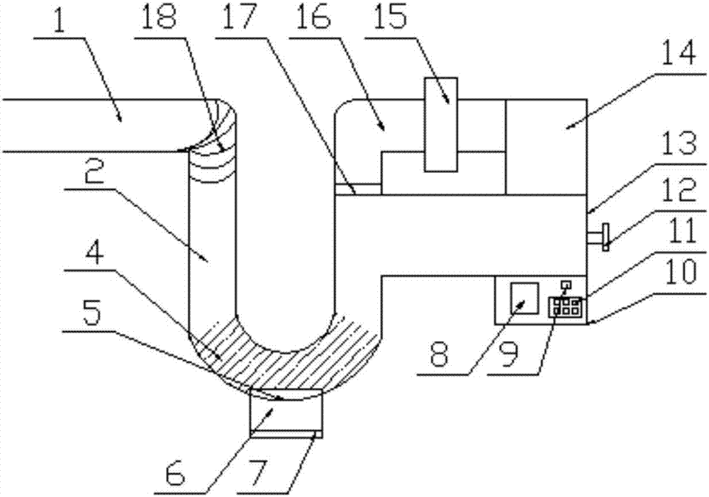
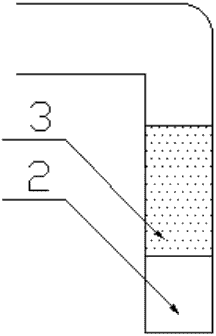
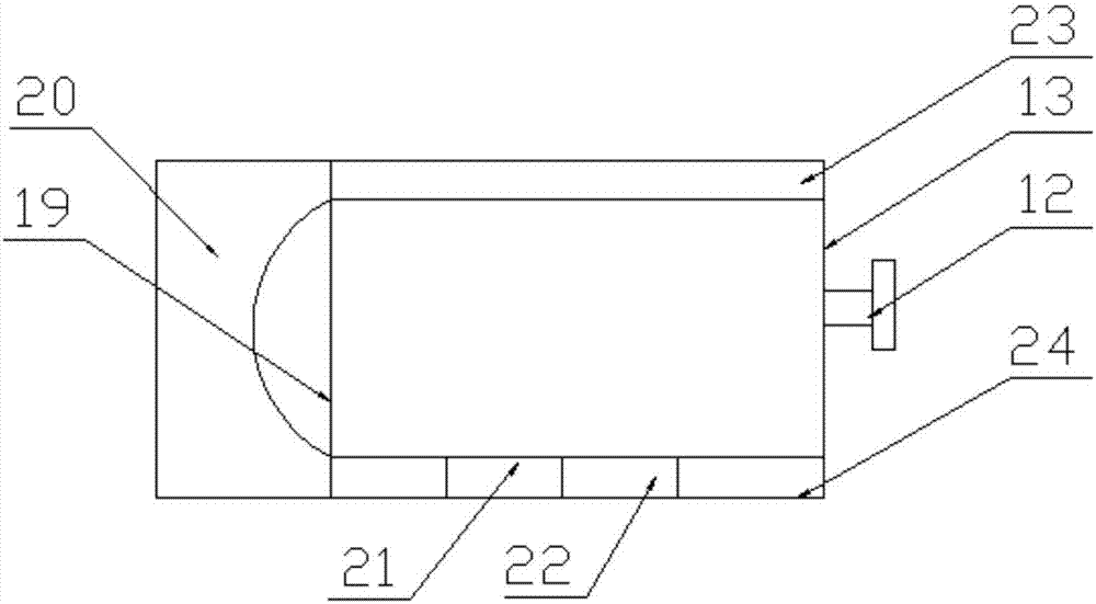

Embodiment Construction

[0026] The following will clearly and completely describe the technical solutions in the embodiments of the present invention with reference to the accompanying drawings in the embodiments of the present invention. Obviously, the described embodiments are only some, not all, embodiments of the present invention. Based on the embodiments of the present invention, all other embodiments obtained by persons of ordinary skill in the art without making creative efforts belong to the protection scope of the present invention.

[0027] An embodiment of the present invention provides an environmental protection utilization device for exhaust heat energy, such as Figure 1-4 As shown, including the automobile exhaust pipe (1), the surface of the automobile exhaust pipe (1) is provided with a metal ferrule (18), the inside of the metal ferrule (18) is threaded, and the lower end of the metal ferrule (18) is provided with an inlet The air pipe (2), the automobile exhaust pipe (1) communic...


PUM


Abstract

The invention provides an exhaust thermal energy environmental protection utilization device, and relates to the field of automobile environmental protection. The environmental protection utilization device comprises an automobile exhaust pipe, a metal hoop is arranged on the surface of the automobile exhaust pipe, an air inlet pipe is arranged at the lower end of the metal hoop, a filter screen is arranged inside the air inlet pipe, a filter cavity is formed in the lower end of the filter screen, a dust collecting box is arranged at the lower end of a screen falling valve, a heating chamber is connected to the other end of the air inlet pipe, a circulation cavity is formed in the heating chamber, a branch pipe is arranged on one side of the circulation cavity, a sensor module is arranged on the surface of the heating chamber, a temperature alertor is arranged on one side of the sensor module, a control chip is electrically connected with a control module, a proportional valve is arranged inside an air outlet pipe, an energy storage area is arranged at the lower end of a purification area, the air outlet pipe is fixedly connected with a drying oven through a catalyst chamber, the above mentioned current automobile exhaust discharge problems are solved, most of the automobile exhaust is discharged directly, the environment is polluted, the exhaust can generate a large amount of heat, the temperature rises, the temperature of this part is emptied directly, and great heat waste is caused.

Description

technical field [0001] The invention relates to the field of automobile environmental protection, in particular to an environmental protection utilization device for exhaust heat energy. Background technique [0002] Automobiles have become an indispensable means of transportation for human beings. Since the birth of the first automobile in 1886, it has brought great convenience to people's life and work, and has also developed into one of the pillars of modern material civilization. However, we should also see that with the rapid development of the automobile industry and the continuous increase in automobile production and ownership, automobiles have also brought air pollution, that is, automobile exhaust pollution. Automobile exhaust is another major factor of air pollution. Automobile exhaust Gasoline contains carbon monoxide, nitrogen oxide, and other solid particles that have adverse effects on the human body, especially leaded gasoline, which is more harmful to the h...

Claims


Application Information

Patent Timeline
IPC IPC(8): F01N5/02F01N13/08F01N3/021F01N3/28
CPCF01N3/021F01N3/28F01N5/02F01N13/08F01N13/082F01N2250/02Y02A50/20Y02T10/12
Inventor 张业勋
Owner 安吉安畅道路施救服务有限公司
Learn More