Segmented serial electric rotor turbofan engine and control method thereof

A turbofan engine, tandem technology, applied in the direction of machine/engine, jet propulsion, etc., can solve the problems of occupying combustion chamber space, prone to surge, low combustion efficiency, etc., to increase combustion space and reduce surge The probability of vibration and the effect of improving combustion efficiency

Inactive Publication Date: 2017-11-17
刘雨棣 +1
View PDF7 Cites 10 Cited by
  • Summary
  • Abstract
  • Description
  • Claims
  • Application Information

AI Technical Summary

Problems solved by technology

In this structure, the nesting parts of the fan rotor, the intermediate pressure compressor rotor, the high pressure compressor rotor and the turbine shaft need to be lubricated by lubricating equipment respectively, and sealing equipment is required between multiple compressors to ensure the sealing performance, and the structure is complicated ; and because the fan rotor, the medium pressure compressor rotor, the high pressure compressor rotor and the turbine shaft are concentrically nested together, each component cannot adjust its own speed in time according to the airflow pressure, and surge phenomenon is prone to occur; at the same time, multiple The mechanical rotor made of nested rotors will pass through the front and rear of the engine. The mechanical rotor needs to pass through the combustion chamber, which occupies the space of the combustion chamber. Therefore, the combustion chamber can only adopt a ring pipe or ring structure with complex shapes, and the combustion efficiency is low.

Method used


Image

  • Segmented serial electric rotor turbofan engine and control method thereof
  • Segmented serial electric rotor turbofan engine and control method thereof
  • Segmented serial electric rotor turbofan engine and control method thereof

Examples


Embodiment Construction

[0045] The following will clearly and completely describe the technical solutions in the embodiments of the present invention with reference to the drawings in the embodiments of the present invention.

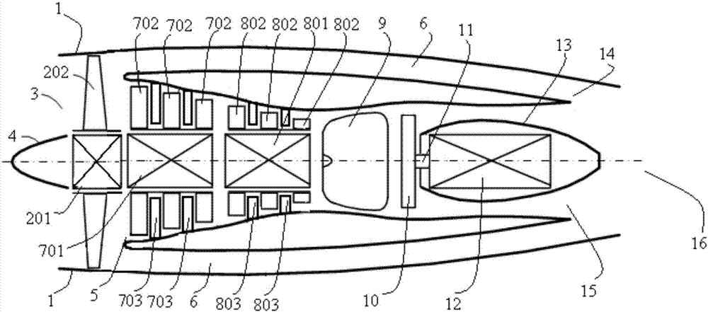
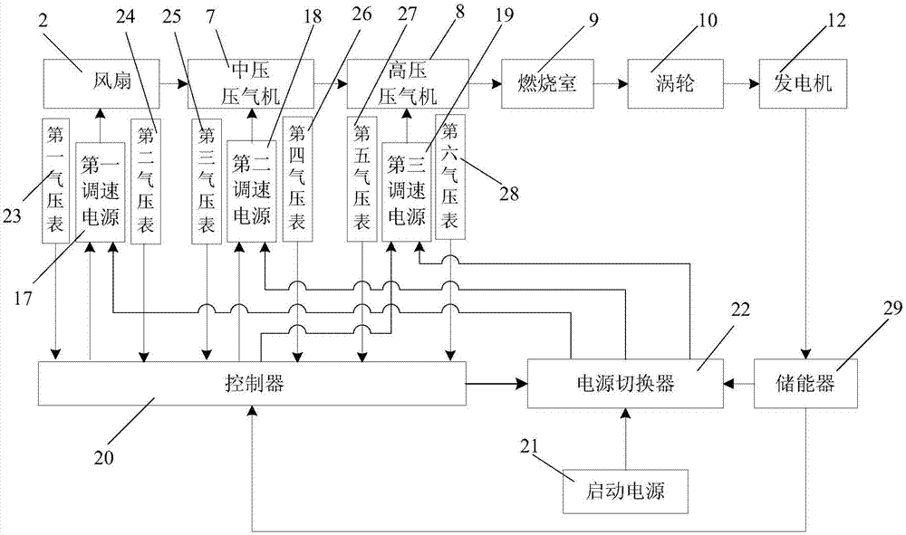
[0046] refer to figure 1 , the segmented tandem electric rotor turbofan engine of the present invention comprises: casing 1, engine inlet 3, fan 2, medium pressure compressor 7, high pressure compressor 8, combustion chamber 9, turbine 10, generator 12 and control system.

[0047] The casing 1 is provided with an engine air inlet 3, and the front portion of the engine air inlet 3 is provided with a fan 2, the fan 2 is an axial fan, and the fan 2 is fixed in the casing 1 by a fan bracket; The middle part is divided into an inner duct 5 and an outer duct 6, the end of the inner duct 5 is provided with an inner duct exhaust port 15, the rear of the outer duct 6 is provided with an exhaust cone 13, and the tail end of the outer duct 6 is provided with a Outer duct exhaust port 1...


PUM


Abstract

The invention belongs to the technical field of aviation gas turbine engines, and discloses a segmented serial electric rotor turbofan engine and a control method thereof. The segmented serial electric rotor turbofan engine comprises an intermediate-pressure gas compressor, a high-pressure gas compressor, a combustion chamber, a turbine, a generator, a first speed adjusting power source, a second speed adjusting power source, a third speed adjusting power source, a controller, a power switcher, a starting power source and the like. A fan is driven by the first speed adjusting power source, the intermediate-pressure gas compressor is driven by the second speed adjusting power source, the high-pressure gas compressor is driven by the third speed adjusting power source, and therefore rotors of the fan, the intermediate-pressure gas compressor and the high-pressure gas compressor have no mechanical connection; the controller adjusts the rotating speeds of the fan, the intermediate-pressure gas compressor and the high-pressure gas compressor in real time according to the inlet and outlet airflow pressure ratios of the fan, the intermediate-pressure gas compressor and the high-pressure gas compressor; the gas compression efficiency is high; the probability that surge happens to the gas compressors can be effectively reduced; and the structure is simple.

Description

technical field [0001] The invention belongs to the technical field of aviation gas turbine engines, and in particular relates to a segmented tandem electric rotor turbofan engine and a control method thereof. Background technique [0002] At present, aviation gas turbofan jet engines are usually composed of air inlet, fan, compressor, combustion chamber, turbine, rotor, nozzle and other components. The air flow enters from the intake port and is compressed by the compressor to produce high-pressure gas; the high-pressure gas is mixed with the fuel in the combustion chamber to form a high-temperature and high-pressure gas flow, which drives the turbine to rotate and is discharged from the engine nozzle to become engine thrust; At the same time, the turbine drives the compressor and the fan to rotate through the rotor, and continuously compresses the air flow entering the intake port to maintain the continuous operation of the engine. [0003] In order to improve the compres...

Claims


Application Information

Patent Timeline
Patent Type & Authority Applications(China)
IPC IPC(8): F02K3/06F02K3/075
CPCF02K3/075F02K3/06
Inventor 刘雨棣杨亚萍
Owner 刘雨棣
Why Eureka
Try Eureka