Driving device and electric tool applying same

A technology for driving devices and power tools, applied in power tools, transmission devices, gear transmission devices, etc., can solve the problems of limiting the reduction ratio of the gearbox and increasing the volume of the gearbox.

Inactive Publication Date: 2017-11-17
JOHNSON ELECTRIC SHENZHEN
View PDF0 Cites 8 Cited by
  • Summary
  • Abstract
  • Description
  • Claims
  • Application Information

AI Technical Summary

Problems solved by technology

Because the output shaft of the motor should have a certain size of outer diameter to be able to withstand a large enough torque, resulting in a large outer diameter of the sun gear and the outer diameter of the inner ring gear, thereby increasing the volume of the entire gearbox and limiting the gear box reduction ratio

Method used


Image

  • Driving device and electric tool applying same
  • Driving device and electric tool applying same
  • Driving device and electric tool applying same

Examples


Embodiment Construction

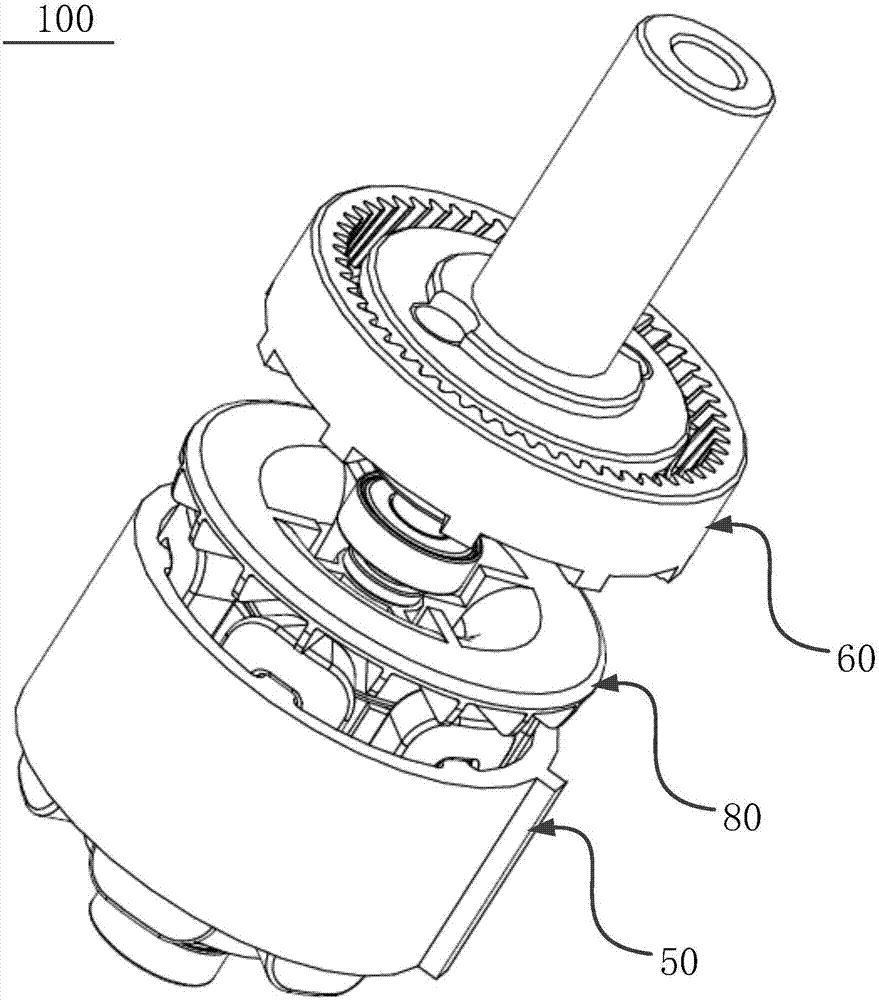
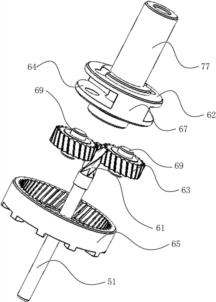
[0030] Such as figure 1 As shown, the present invention provides a driving device 100 including a motor 50 and a planetary gearbox 60 . The gear box 60 is installed on the output end of the motor 50, decelerates the output of the motor 50 and then outputs it to the outside.

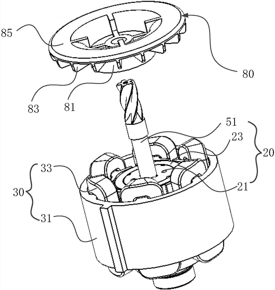
[0031] Such as Figure 1 to Figure 2 As shown, the motor 50 includes a stator 30 and a rotor 20 , and the stator 30 includes a stator core 31 and a winding 33 wound on the stator core 31 . The stator core 31 includes an annular yoke and a plurality of teeth protruding inward from the yoke. Winding slots are formed between adjacent teeth, and windings 33 are wound on the teeth. The rotor 20 includes a rotating shaft 51 , a rotor core 21 fixed to the rotating shaft 51 , a permanent magnet 23 mounted to the rotor core 21 , and the like. There is a gap between the teeth of the rotor core 23 and the stator core 31 , allowing the rotor 20 to rotate relative to the stator 30 . In this embodiment, the stator ...


PUM


Abstract

The invention provides a driving device comprising a motor being a single-phase motor and a gearbox. The gearbox comprises a sun gear, a plurality of planetary gears surrounding and engaged with the sun gear, and a plurality of internal gear rings surrounding and engaged with the plurality of planetary gears, wherein the sun gear integrally forms a rotating shaft on the motor. The invention further provides an electric tool comprising the driving device, a work head driven by the driving device and an impact unit arranged between the driving device and the work head. In the driving device and the electric tool applying the driving device, the sun gar is combined with the motor rotating shaft and an integrally-formed gear shaft is formed, so a number of teeth of the sun gear can be reduced to 5 or less; and gearbox transmission ratio can be effectively improved when a maximum geometrical external diameter is remained the same.

Description

technical field [0001] The invention relates to the field of motor drive technology, in particular to a driving device with a large speed ratio reduction structure and an electric tool using the driving device. Background technique [0002] The planetary gear reducer is often used to reduce the output of the motor and then output it to the outside. The planetary gear reducer includes a sun gear, an internal ring gear, several planetary gears and a turntable driven by the several planetary gears, and the internal ring gear surrounds the sun gear. The several planetary gears surround the sun gear, and each planetary gear meshes with the sun gear and the ring gear at the same time. The sun gear is fixedly sleeved to the output shaft of the motor and rotates with the output shaft of the motor. Therefore, when the motor is running, the sun gear drives the planet gear, and the planet gear will revolve around the sun gear under the constraint of the ring gear, and this revolution...

Claims


Application Information

Patent Timeline
Patent Type & Authority Applications(China)
IPC IPC(8): F16H57/023
CPCB25B21/026B25F5/001B25F5/008F16H1/28H02K1/146H02K1/2706H02K7/116H02K9/06F16H57/023
Inventor 李越塔静宁余斌栗秋梅
Owner JOHNSON ELECTRIC SHENZHEN
Why Eureka
Try Eureka