
Direct-acting three-station isolation switch device

An isolation switch, three-station technology, applied in electrical switches, high-voltage/high-current switches, high-voltage air circuit breakers, etc., can solve the problem of difficulty in achieving solid-sealed pole sealing, disadvantageous switchgear miniaturization, and inability to achieve modular design. and other problems, to achieve the effect of satisfying the miniaturization of equipment, simple structure and reducing the local defense value

Inactive Publication Date: 2017-11-17
国电博纳(北京)电力设备有限公司
View PDF8 Cites 2 Cited by
  • Summary
  • Abstract
  • Description
  • Claims
  • Application Information

AI Technical Summary

Problems solved by technology

[0004] Although rotary three-position isolating switchgear is widely used, there are also common problems. First, it requires a large space and is difficult to use in a relatively narrow space, which is not conducive to the miniaturization of switchgear.
Second, most rotary three-position isolating switchgear cannot realize modular design in structure, and the electric field distribution is not uniform
Third, when the rotary three-position isolating switch equipment is directly applied to the solid-sealed pole, it is difficult to achieve the sealing of the solid-sealed pole

Method used


Image

  • Direct-acting three-station isolation switch device
  • Direct-acting three-station isolation switch device
  • Direct-acting three-station isolation switch device

Examples


Embodiment 1

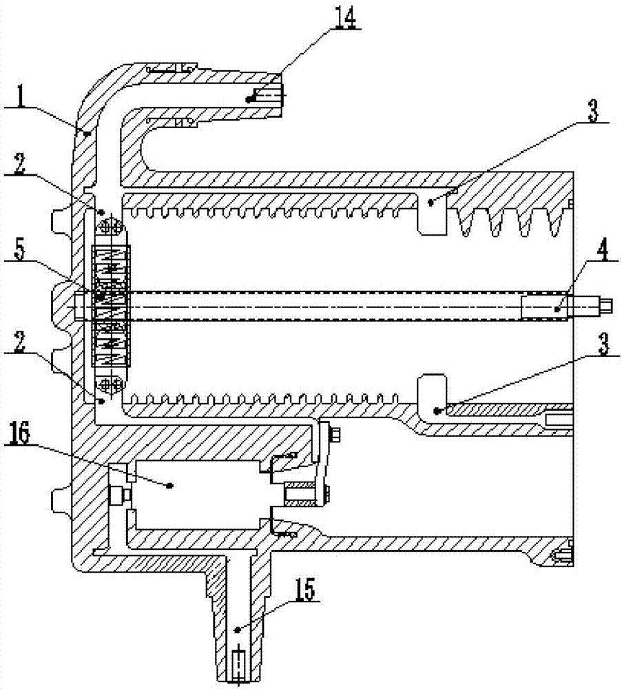
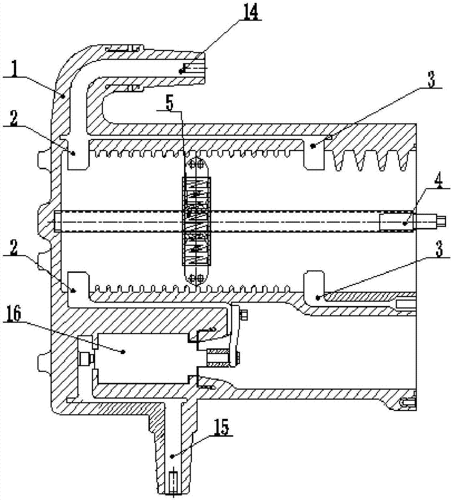
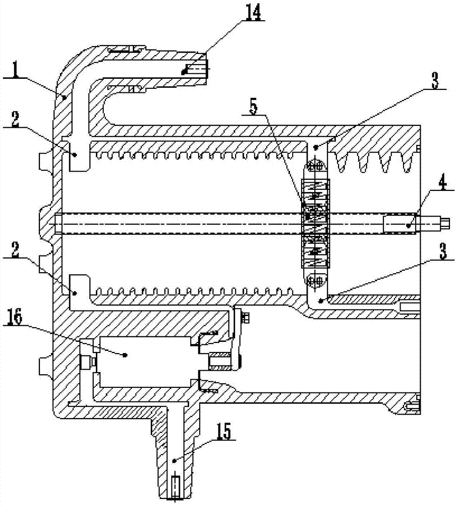
[0041] Such as Figure 1-8 As shown, a direct-acting three-position isolating switchgear includes a solid-sealed pole 1, and the solid-sealed pole 1 is provided with an isolation static contact 2, a grounding static contact 3, and a drive screw 4 along a straight line;

[0042] The isolated static contact 2 and the grounding static contact 3 are arranged at a certain interval, and both are arranged in pairs up and down;

[0043] The transmission screw 4 is located between two isolated static contacts 2, and the transmission screw 4 is provided with a sliding contact 5; the sliding contact 5 can rotate between the isolation static contact 2 and the grounding static The contacts 3 reciprocate and are intermittently connected with them; both ends of the transmission lead screw 4 are rotatably connected with the embedded pole 1 , and one end of the screw 4 extends out of the embedded pole 1 .

[0044] The sliding contact 5 includes a moving contact knife 6 , a support member 7 , ...

Embodiment 2

[0057] This embodiment is basically the same as Embodiment 1, except that: the embedded pole 1 is integrally cast and formed by transparent insulating material; the material of the embedded pole 1 is polycarbonate; and because the embedded pole 1 It is transparent, so the actual position of the three-position switchgear can be directly observed. There is no observation window 17 on the solid-sealed pole 1, such as Figure 9 shown.


PUM


Abstract

The invention provides a direct-acting three-station isolation switch device, which comprises a solid-sealed polar pole. The solid-sealed polar pole is internally provided with isolated static contacts, grounding static contacts and a drive screw rod in the linear direction. The isolated static contacts and the grounding static contacts are arranged at a certain interval, and are arranged in pairs up and down respectively; the drive screw rod is arranged between the two isolated static contacts; the drive screw rod is provided with a sliding contact; the sliding contact can reciprocate between the isolated static contacts and the grounding static contacts with rotation of the drive screw rod and are in intermittent connection with the isolated static contacts and the grounding static contacts; and the two ends of the drive screw rod are in rotation connection with the solid-sealed polar pole, and one end thereof extends out of the solid-sealed polar pole. The direct-acting three-station isolation switch device is simple and compact in structure, can meet requirement for equipment miniaturization, realizes modular assembly and facilitates seal of the solid-sealed polar pole.

Description

technical field [0001] The invention belongs to the field of switchgear, in particular to a direct-acting three-position isolating switchgear. Background technique [0002] In the switchgear, the three-position isolating switchgear is widely used because it has the three-position functions of closing, isolating, and grounding, which can not only ensure the safe operation of the switch, but also ensure the safety of the operator. [0003] At present, the common three-position isolating switch equipment is mainly a rotary knife switch structure, such as ABB's SafeRing type and Areva's FBX type ring main unit. [0004] Although rotary three-position isolating switchgear is widely used, there are common problems. First, it requires a large space and is difficult to use in a relatively narrow space, which is not conducive to the miniaturization of switchgear. The second is that most rotary three-position isolating switchgear cannot realize modular design in structure, and the el...

Claims


Application Information

Patent Timeline
IPC IPC(8): H01H33/666H01H33/664
CPCH01H33/666H01H33/664
Inventor 郭会勇高辉高国宪
Owner 国电博纳(北京)电力设备有限公司
Learn More