

Square head cutting machining device for shaft part and square head machining method for shaft part
A technology of cutting processing and parts, applied in metal processing equipment, other manufacturing equipment/tools, measuring/indicating equipment, etc., can solve the problem of slow processing speed, low efficiency, difficulty in meeting the needs of large-scale and high-efficiency production and processing, etc. problem, to achieve the effect of precise processing and high efficiency
- Summary
- Abstract
- Description
- Claims
- Application Information
AI Technical Summary
Problems solved by technology
Method used
Image

Examples
Embodiment 1
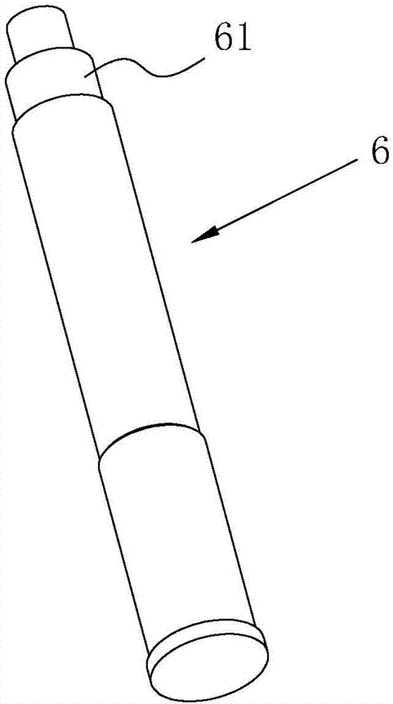
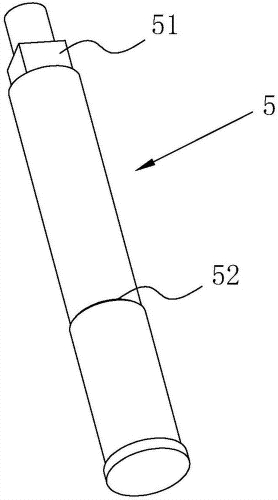
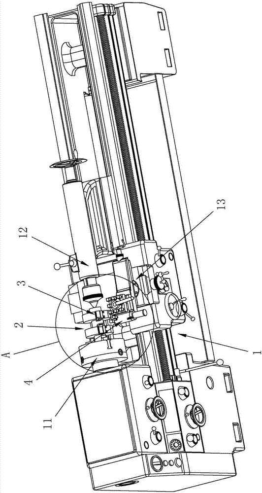
[0042] A square head cutting processing equipment for shaft parts, refer to image 3 as well as Figure 4 , comprising lathe 1, on the rotating shaft of lathe 1, be provided with the rotating cutterhead 2 that follows rotating shaft and rotate synchronously, the outer edge of rotating cutterhead 2 is equipped with cutting tool 3, is installed on the tool seat 13 of lathe 1 side simultaneously The fixture 4 of the fixed shaft part 5, the shaft part 5 is fixed on the tool fixture 4 so that the processing end of the shaft part 5 faces the rotating cutter head 2, and when the rotating cutter head 2 rotates, the cutting tool 3 cuts the shaft part 5 for processing.
[0043] The rotating cutterhead 2 is fixed on the rotating shaft of the lathe 1 through the three-jaw chuck 11, and the tailstock 12 of the lathe 1 presses against the other end of the rotating cutterhead 2 relative to the three-jaw chuck 11 to enhance the stability of the rotating chuck.
[0044] refer to Figure 4 as...
Embodiment 2
[0052] A method for processing a square head of a shaft part, using the square head cutting processing equipment for a shaft part in Embodiment 1, specifically:
[0053] Step 1: Adjust the distance between the two blades 31 on the rotating cutter head 2
[0054] Loosen the third fastener 232 on the rotating disk 22, adjust the position of the blade 31 in the mounting groove 221 relative to the axial direction of the rotating disk 22, and adjust the distance between the two blades 31 according to the scale 24 on the cutter head and the blade 31. The distance is accurately determined, and the third fastener 232 is tightened to fix the blade 31 again;
[0055] Step 2: Adjust the position of the axis of the mounting sleeve 41 relative to the cutting tool 3
[0056] Adjust and move the slide box of the lathe 1 along the axial direction of the main shaft of the lathe 1, and then drive the installation sleeve 41 to move through the tool seat 13, adjust the axis of the installation s...
PUM
 Abstract
Description
Claims
Application Information