Three-end input/output mechanism
A technology of output mechanism and output action, which is applied in the directions of packaging machines, transportation and packaging, and strapping machine parts, etc., which can solve the problems of high design cost, large structure size, slow response speed, etc., and achieve quick response and small mechanism size , detect reliable effects
- Summary
- Abstract
- Description
- Claims
- Application Information
AI Technical Summary
Problems solved by technology
Method used
Image

Examples
Embodiment 1
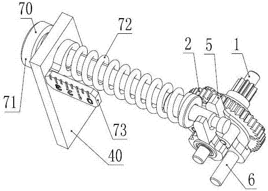
[0041] Such as figure 1 , figure 2 , image 3 , Figure 4 As shown, the aforesaid three-terminal input / output mechanism is used as a torque comparator for an automatic cable tie tool, the internal and external gears 2 drive the cable tie tensioning wheel 30 through a tensioning gear 31, and the planetary wheel base 5. Drive the cutter 8 through the dial pin 6 fixed on the planetary wheel base 5; the planetary wheel base motion control device 70 is used to adjust the tightening force of the object to be bound, twist the adjusting screw 71, and the vernier 73 moves along the axial direction of the adjustment screw 71, the vernier 73 compresses or releases the adjustment spring 72, the elastic force of the adjustment spring 72 acts on the slider 74, and the slider 74 then moves the adjustment spring 72 The elastic force acts on the fork-shaped structure above the planetary wheel base 5 and makes the fork-shaped structure above the planetary wheel base 5 lock the planetary whe...
Embodiment 2
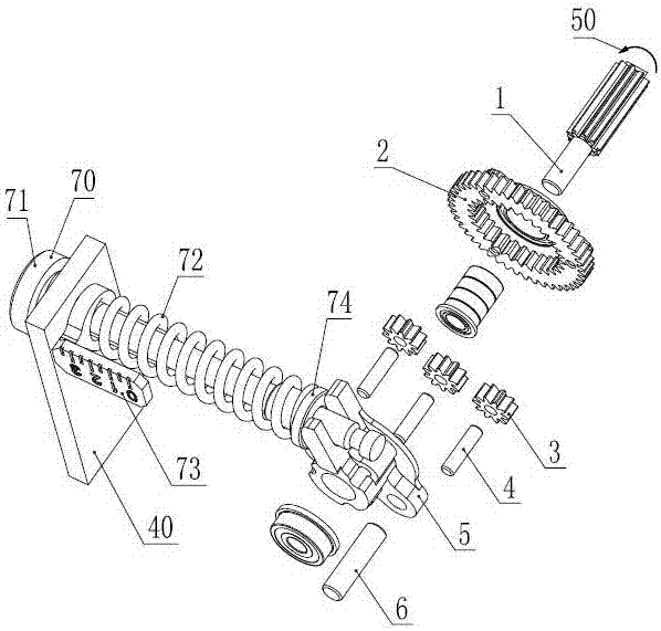
[0045] Such as Figure 5 , Image 6 As shown, the aforesaid three-terminal input / output mechanism is used as a torque comparator for an automatic cable tie tool, the external power is input from the sun gear 1, and the sun gear 1 is pressed figure 2 Rotate in the direction of 50 as shown, the internal and external gear 2 drives the cable tie tensioning wheel 30 through the tensioning gear 31, the planetary wheel base motion control device 70 is used to adjust the tightening force of the object to be bound, and the slider 74 is Under the action of the elastic force of the adjustment spring 72, the rising edge of the planetary wheel base 5 whose shape is a cam profile contacts and locks the planetary wheel base 5; when the sun gear 1 rotates, the motion of the planetary wheel base is controlled The slider 74 of the device 70 locks the planetary wheel base 5, and the inner and outer gears 2 drive the strap tensioning wheel 30 through the tightening gear 31. When the strap tight...
Embodiment 3
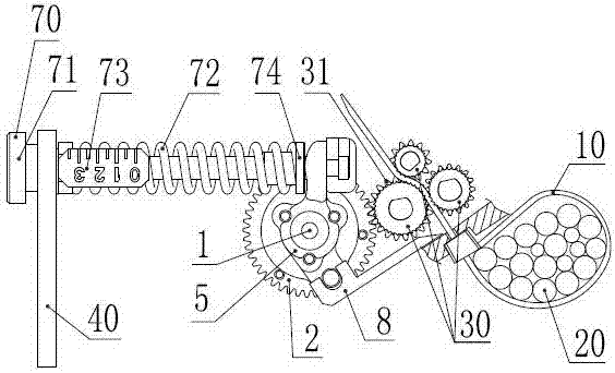
[0049] Such as Figure 9 , Figure 10 Shown: Utilizing the above-mentioned three-terminal input / output mechanism that can convert the torque borne by the internal and external gears 2 to the change of the rotational position of the planetary wheel base 5, a sensor 9 is added to detect the planetary wheel base 5 Whether to act to determine whether the binding action of the automatic cable tie tool is successful; the working principle is: the external power drives the sun gear 1 to press figure 2 Rotate in the direction of 50 as shown, the internal and external gear 2 drives the tensioning wheel 30 through the tensioning gear 31, the planetary wheel base motion control device 70 sets the tensioning force of the cable tie, and the planetary wheel base 5 passes through the dial pin 6 Drive the cutter 8 to cut off the cable tie; if there is a cable tie to enter the tension wheel 30 of the automatic cable tie tool, and when the cable tie tension reaches the set value of the planet...
PUM
 Abstract
Description
Claims
Application Information
 - R&D
- Intellectual Property
- Life Sciences
- Materials
- Tech Scout
- Unparalleled Data Quality
- Higher Quality Content
- 60% Fewer Hallucinations
Browse by: Latest US Patents, China's latest patents, Technical Efficacy Thesaurus, Application Domain, Technology Topic, Popular Technical Reports.
© 2025 PatSnap. All rights reserved.Legal|Privacy policy|Modern Slavery Act Transparency Statement|Sitemap|About US| Contact US: help@patsnap.com