
Flash detection system

A detection system and technology to be detected, applied in biological testing, material inspection products, chemiluminescence/bioluminescence, etc., can solve the problems of pipelines that cannot be cleaned, cannot detect flash reagents, cleaning agent residues, etc., and achieve low cost , High reuse rate, simple liquid path

Pending Publication Date: 2017-11-21
苏州翊讯生物科技有限公司
View PDF9 Cites 0 Cited by
  • Summary
  • Abstract
  • Description
  • Claims
  • Application Information

AI Technical Summary

Problems solved by technology

Although the device in this document can realize automatic chemiluminescence immunoassay, there will be cleaning agent residue after cleaning, the pipeline cannot be cleaned, and the flash reagent cannot be detected

Method used


Image

  • Flash detection system
  • Flash detection system

Examples


Embodiment 1

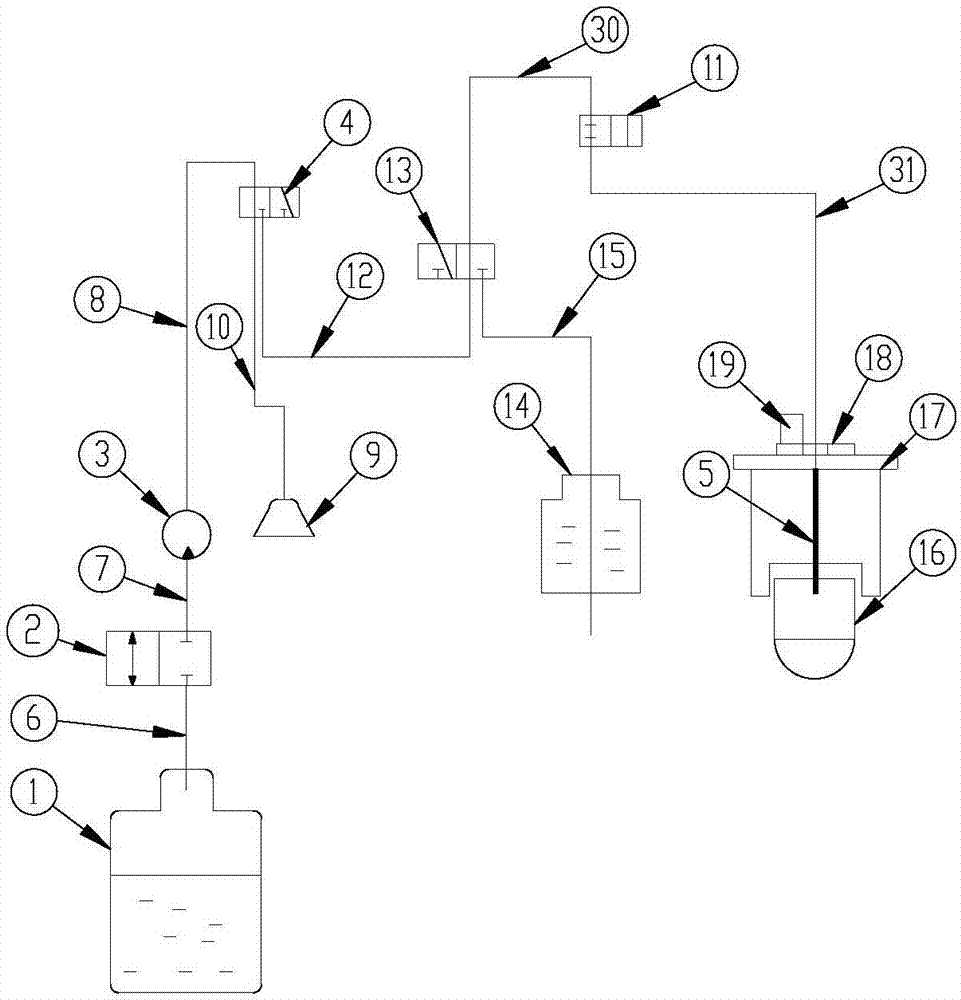
[0020] See attached figure 1 As shown, a flash detection system in this embodiment includes a cleaning system for picking up, filling and drying the cleaning solution, a filling system for picking up and filling the detection reagent, and a storage system to be tested. The pool 16 of the liquid to be detected, and the detection system for detecting the object to be tested, the maintenance and functions of the various systems are realized by connecting the filling system, the cleaning system and the detection system with pipelines. The inner and outer walls of the pool 16 to be detected are both opaque and completely black.

[0021] The cleaning system includes a cleaning liquid bucket 1, a two-way valve one 2, a plunger pump 3, a three-way valve one 4, a filling needle 5, a three-way valve two 13 and a two-way valve two 11, and the cleaning liquid bucket 1 The outlet of the two-way valve one 2 is connected with the inlet of the two-way valve one 2 through the pipeline one 6, ...

Embodiment 2

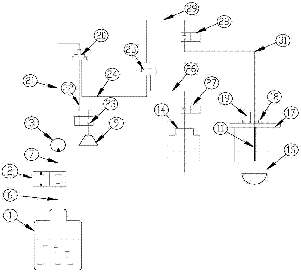
[0027] See attached figure 2 As shown, a flash detection system in this embodiment includes a cleaning system for picking up, filling and drying the cleaning solution, a filling system for picking up and filling the detection reagent, and a storage system to be tested. The pool 16 of the liquid to be detected, and the detection system for detecting the object to be tested, the maintenance and functions of the various systems are realized by connecting the filling system, the cleaning system and the detection system with pipelines. The inner and outer walls of the pool 16 to be detected are both opaque and completely black.

[0028] The cleaning system includes a cleaning liquid tank 1, a two-way valve-2, a plunger pump 3, a tee joint-20 and a filling needle 5, and the outlet of the cleaning liquid tank 1 and the inlet of the two-way valve-2 pass through a pipeline One 6 is connected, the outlet of the two-way valve one 2 is connected with the inlet of the plunger pump 2 thro...


PUM


Abstract

The invention discloses a flash detection system which comprises a cleaning system, a filling system, a tank to be detected and a detection system. The cleaning system is used for picking, filling and blow-drying cleaning liquid, the filling system is used for picking and filling detection reagents, the tank to be detected contains liquid to be detected, and the detection system is used for detecting objects to be detected. Maintenance and functions of the systems are realized by connecting the filling system, the cleaning system and the detection system through a pipeline, the detection system comprises a light-tight cylinder arranged above a detection cell, the light-tight cylinder is overlapped with the center line of the detection cell, a rapidly openable shutter is arranged above the light-tight cylinder, a photomultiplier is arranged above the shutter, and a filling needle sequentially penetrates the shutter and the light-tight cylinder and is suspended above the detection cell. By the aid of the filling needle arranged above the detection cell, the detection reagents can be rapidly filled, the shutter is rapidly opened to obtain detection results, the flash detection system is applicable to flash detection, the pipeline can be blow-dried by the cleaning system capable of blow-drying the cleaning liquid after a liquid path is cleaned, residues are avoided, and the pipeline is cleaned up.

Description

technical field [0001] The invention relates to the field of medical equipment, in particular to a flash detection system. Background technique [0002] In recent years, with the development of immune technology, chemiluminescence immunoassay technology has achieved rapid development. The luminescence types of chemiluminescence reactions are usually divided into two types: flash type and glow type; flash type luminescence The time is very short, only a few tenths of a second to a few seconds. The glow type is also called the continuous type, and the luminous time is from a few minutes to tens of minutes, or several hours or longer. [0003] Another example is the Chinese patent document CN106546758A which discloses a fully automatic chemiluminescent immunoassay analyzer and its liquid circuit system, wherein the system uses a plunger pump and a solenoid valve to pick up and fill samples and pick up and inject luminescent acid and alkali solutions. Refill, and use washing li...

Claims


Application Information

Patent Timeline
Patent Type & Authority Applications(China)
IPC IPC(8): G01N33/53G01N21/76
CPCG01N21/76G01N33/53
Inventor 华斌陈任远任传路张建新王宇胡胜利
Owner 苏州翊讯生物科技有限公司
Learn More