Output over-current and short-circuit protection circuit and electronic equipment

A short-circuit protection circuit and protection circuit technology, applied in the field of output overcurrent and short-circuit protection circuits, electronic equipment, can solve the problems of long response time, high power consumption, increased power consumption, etc., to achieve fast response speed, long service life, The effect of power supply security

Active Publication Date: 2017-11-21
SANLI VIDEO FREQUENCY SCI & TECH SHENZHEN
View PDF6 Cites 5 Cited by
  • Summary
  • Abstract
  • Description
  • Claims
  • Application Information

AI Technical Summary

Problems solved by technology

The relay is a mechanical switch. It takes at least tens of milliseconds from current detection and sampling to control its action to close. The response time is too long, and such a long response time may cause damage to the controller power supply and peripherals.
[0007] 3. Short life
When the relay is under load, the life of repeated switching is only about tens of thousands of times, which is a serious problem for equipment that requires trouble-free operation for three years, five years or even longer.
[0008] 4. High power consumption
When the relay is closed, it needs a certain holding current, which will increase the power consumption; in addition, the sampling resistor connected in series, the current will all flow through the sampling resistor, which will also increase the additional power consumption of the system
[0009] 5. Inflexible control
[0011] 1. High power consumption
It is also a series sampling resistor, which will increase the extra power consumption of the system
[0012] 2. Inflexible control

Method used


Image

  • Output over-current and short-circuit protection circuit and electronic equipment
  • Output over-current and short-circuit protection circuit and electronic equipment
  • Output over-current and short-circuit protection circuit and electronic equipment

Examples


Embodiment 1

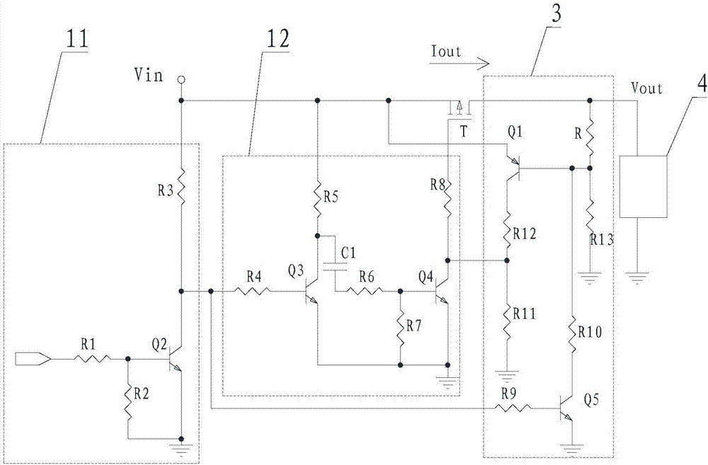
[0042] Please refer to image 3 , Embodiment 1 of the present invention is:

[0043] An output overcurrent and short circuit protection circuit includes a drive circuit 1, a MOS transistor T and a protection circuit 3. The drive circuit 1 includes an IO drive unit 11 and a pulse drive unit 12. The IO drive unit 11 includes: a first resistor R1, a second resistor R2, a third resistor R3 and a second transistor Q2. The pulse drive unit 12 includes: The fourth resistor R4, the fifth resistor R5, the sixth resistor R6, the seventh resistor R7, the eighth resistor R8, the capacitor C1, the third transistor Q3 and the fourth transistor Q4. The protection circuit 3 includes a ninth resistor R9, a fifth transistor Q5, a tenth resistor R10, a first transistor Q1, a sampling resistor R, an eleventh resistor R11, a twelfth resistor R12 and a thirteenth resistor R13.

[0044] The drain of the MOS transistor T is used for connecting the load 4, and the source of the MOS transistor T is ...

Embodiment 2

[0072] An electronic device includes a load and the output over-current and short-circuit protection circuit described in Embodiment 1, and the load is connected to the output over-current and short-circuit protection circuit.

[0073] In summary, an output overcurrent and short circuit protection circuit and an electronic device provided by the present invention have the advantages of low cost, fast response, flexible control, long life, high reliability, and low power consumption.


PUM


Abstract

The invention provides an output over-current and short-circuit protection circuit, which comprises a driving circuit, an MOS transistor and a protection circuit, and is characterized in that the protection circuit comprises a first triode and a sampling resistor, the driving circuit is connected with a grid electrode of the MOS transistor, a drain electrode of the MOS transistor is connected with a load, a source electrode of the MOS transistor is used for being connected to a power supply, the driving circuit is used for being connected to an IO interface of a controller, an emitting electrode of the first triode is connected with the source electrode of the MOS transistor, a base electrode of the first triode, the sampling resistor and the drain electrode of the MOS transistor are sequentially connected, and a collecting electrode of the first triode is connected with the driving circuit. The MOS transistor is adopted to act as an electronic switch, the triode and the sampling resistor form the protection circuit, and the source electrode and the drain electrode of the MOS transistor are directly connected with the protection circuit in parallel. The output over-current and short-circuit protection circuit has the advantages of low cost, high response speed, high reliability and low power consumption. The invention further relates to electronic equipment, which comprises a load and the output over-current and short-circuit protection circuit, wherein the load is connected with the output over-current and short-circuit protection circuit.

Description

technical field [0001] The invention relates to the technical field of circuit protection, in particular to an output overcurrent and short circuit protection circuit and an electronic device. Background technique [0002] In some security control systems, it is sometimes necessary to connect some external devices, such as smoke sensors, weather sensors, temperature sensors, sound and light alarms, cameras, etc. This will inevitably involve the power supply of peripherals, and it is multi-channel power supply. The power supply of such peripherals is usually provided by the system controller with multiple power supply interfaces exposed to the outside, and users can connect these peripherals by themselves through plugs and cables. If a certain peripheral fails, or the user accidentally short-circuits the power supply output when connecting the peripheral, and there is no over-current and short-circuit protection circuit in the controller, it is likely to cause damage to the ...

Claims


Application Information

Patent Timeline
Patent Type & Authority Applications(China)
IPC IPC(8): H02H3/08
CPCH02H3/08
Inventor 陶华波
Owner SANLI VIDEO FREQUENCY SCI & TECH SHENZHEN
Why Eureka
Try Eureka