
Visual pressure stabilization trachea cannula

A technology for tracheal intubation and pressure stabilization, which is applied in the direction of tracheal intubation and respirators, etc., can solve the problems of increasing tracheal intubation-related complications, pressure increase, and increasing patient discomfort, so as to reduce tracheal intubation Effects of related complications, avoiding excessive changes, and reducing workload

Inactive Publication Date: 2017-11-24
黄立宁
View PDF9 Cites 5 Cited by
  • Summary
  • Abstract
  • Description
  • Claims
  • Application Information

AI Technical Summary

Problems solved by technology

Too low cuff pressure can also cause leaks in the ventilator circuit, causing hypoventilation
Excessive cuff pressure will cause tracheal mucosal edema, ischemia, and even necrosis, and patients will have cough and throat discomfort after surgery, which will increase patient discomfort and reduce patient satisfaction
For sensitive patients who have been operated for a long time or in the ICU with a tube for a long time, too high cuff pressure can cause severe tracheal stenosis after extubation, and surgery may even be required in the later stage
[0003] The pressure in the cuff will decrease due to cuff leakage in critically ill patients who have long-term operations or need to wear tubes for a long time. If the cuff is not inflated in time, it will cause air leakage and increase the risk of aspiration
Surgical methods such as laparoscopy will increase the pressure in the cuff and increase the incidence of postoperative throat complications; body position changes will also have a certain impact on the cuff pressure. There is a lack of feasible monitoring methods, and it is easily ignored by clinicians, causing postoperative discomfort for patients, increasing complications related to endotracheal intubation, and causing unnecessary economic burden for patients

Method used


Image

  • Visual pressure stabilization trachea cannula
  • Visual pressure stabilization trachea cannula

Examples


Embodiment Construction

[0014] The technical solutions in the embodiments of the present invention are clearly and completely described below in conjunction with the accompanying drawings in the embodiments of the present invention. Obviously, the described embodiments are only part of the embodiments of the present invention, not all of them. Based on the embodiments of the present invention, all other embodiments obtained by persons of ordinary skill in the art without making creative efforts belong to the protection scope of the present invention.

[0015] In the following description, a lot of specific details are set forth in order to fully understand the present invention, but the present invention can also be implemented in other ways different from those described here, and those skilled in the art can do it without departing from the meaning of the present invention. By analogy, the present invention is therefore not limited to the specific examples disclosed below.

[0016] As shown in the ...


PUM


Abstract

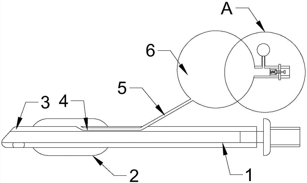
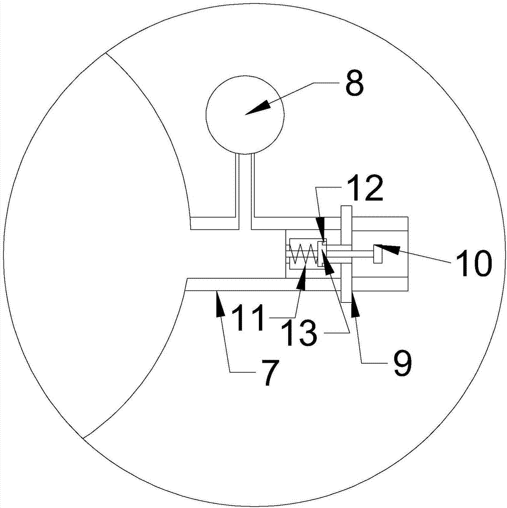
The invention discloses a visual pressure stabilization trachea cannula, and relates to the field of medical instruments. The visual pressure stabilization trachea cannula comprises a cannula body, a sleeve bag, an air storage bag and a one-way valve, the sleeve bag is arranged at the end of the cannula body, the air storage bag is communicated with the sleeve bag through a catheter and a pipe wall catheter, the one-way valve is arranged on the air storage bag, air is inflated into the air storage bag by the one-way valve, the pipe wall catheter is arranged in the wall of the cannula body, and the gas capacity ratio of the air storage bag to the sleeve bag is (4-8):1. According to the visual pressure stabilization trachea cannula, the high-capacity elastic air storage bag can automatically inflate air into the catheter sleeve bag, so that pressure change in the catheter sleeve bag is buffered when the sleeve bag leaks air as intubation time is prolonged, risks of aspiration pneumonia and breathing circle leakage are reduced, safety of patients is improved, various complications caused by pressure of the sleeve bag in a perioperative period are reduced, and the workload of medical staff is also relieved.

Description

technical field [0001] The invention relates to a visible pressure-stabilizing trachea intubation tube, which relates to the field of medical equipment. Background technique [0002] At present, the commonly used inflation method in clinical practice is that the operator squeezes the exposed small detection balloon connected with the balloon to estimate the pressure of the catheter balloon. Due to the difference of personal experience, the cuff pressure produced in clinical anesthesia work varies greatly. . Too low cuff pressure will cause various oropharyngeal secretions (including: refluxed gastric contents, bloody secretions caused by surgery, etc.) Burden, heavy person even life-threatening. Too low cuff pressure can also cause leaks in the ventilator circuit, resulting in hypoventilation. Excessive cuff pressure will cause edema, ischemia, and even necrosis of the tracheal mucosa, and postoperative cough and pharyngeal discomfort will increase patient discomfort and ...

Claims


Application Information

Patent Timeline
IPC IPC(8): A61M16/04
CPCA61M16/0463A61M16/0402A61M16/0488
Inventor 黄立宁李旭泽邸丽丽康荣田
Owner 黄立宁
Learn More