Bodywork Y-direction positioning and locking mechanism for welding assembly line

A welding line and vehicle body technology, applied in the field of two-point positioning locking mechanism, can solve the problems that are difficult to meet the stability requirements of equipment, affect the positioning accuracy of the welding line, and uneven clamping force, etc., and achieve compact structure and space occupation Small, consistent clamping force

Active Publication Date: 2017-11-24
HEFEI JEE INTELLIGENT EQUIP CO LTD
View PDF2 Cites 4 Cited by
  • Summary
  • Abstract
  • Description
  • Claims
  • Application Information

AI Technical Summary

Problems solved by technology

[0003] At present, most of the welding lines use cylinder-driven single four-bar linkage mechanism to clamp a point of positioning locking, which is called single-point positioning locking mechanism. The single-point positioning locking method is difficult to meet the stability requirements of all equipment. For For equipment with high stability requirements, multiple single-point positioning locking mechanisms will be used for joint positioning
However, multiple single-point positioning locking mechanisms are controlled separately by multiple cylinders, which will cause poor synchronization during the locking process, which will lead to uneven clamping force and affect the positioning accuracy of the welding line.

Method used


Image

  • Bodywork Y-direction positioning and locking mechanism for welding assembly line
  • Bodywork Y-direction positioning and locking mechanism for welding assembly line
  • Bodywork Y-direction positioning and locking mechanism for welding assembly line

Examples


Embodiment Construction

[0022] The embodiments of the present invention are described in detail below. This embodiment is implemented on the premise of the technical solution of the present invention, and detailed implementation methods and specific operating procedures are provided, but the protection scope of the present invention is not limited to the following implementation example.

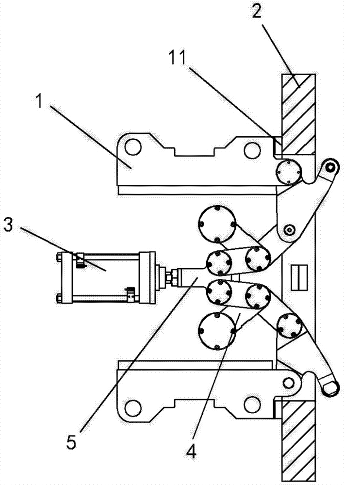
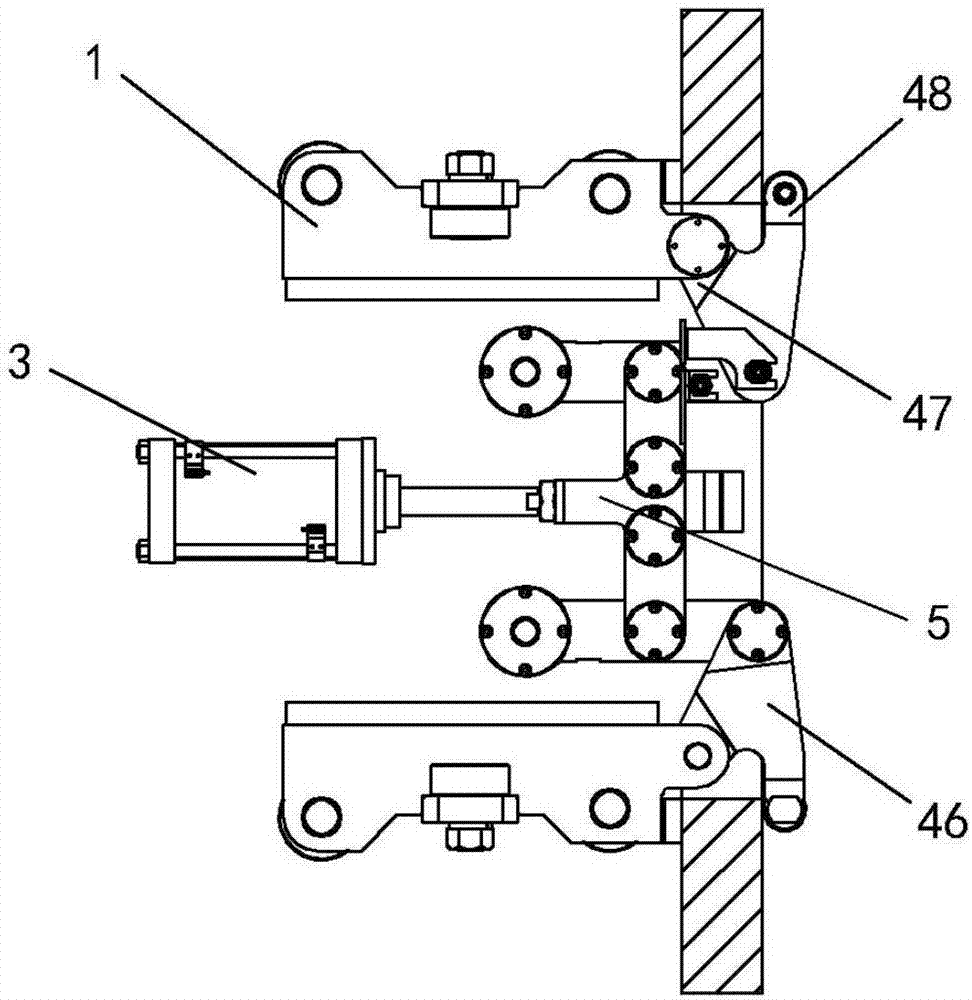
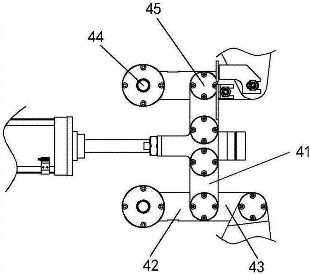
[0023] Such as Figure 1 ~ Figure 3 As shown, the structural relationship is as follows: it includes two symmetrically arranged mounting bases 1 and a cylinder 3 located between the two mounting bases 1. The mounting base 1 and the cylinder 3 are fixedly connected to the fixed working platform, and are used to control the equipment 2 respectively. Fix the limit and drive the link mechanism to lock the device 2. The two link mechanisms 4 are symmetrically connected to the end of the output shaft of the cylinder 3; To the tail end of the first connecting rod 41, and the end structure 46 hinged to the tail end of the...


PUM


Abstract

The invention relates to the technical field of positioning mechanisms and discloses a bodywork Y-direction positioning and locking mechanism for a welding assembly line. Mounting seats and an air cylinder are fixedly connected to a fixed operating platform, and two link mechanisms are symmetrically connected to the tail end of an output shaft of the air cylinder. Front ends of each second connecting rod and a corresponding third connecting rod are connected to the tail end of a corresponding first connecting rod through a corresponding rotating point to form one link mechanism along with a tail end structure hinged to the tail end of the corresponding third connecting rod, the front end of each first connecting rod is connected to the tail end of the output shaft of the air cylinder through the corresponding rotating point, and the tail end of each third connecting rod is connected to the fixed operating platform through a fixing point. The bodywork Y-direction positioning and locking mechanism has advantages that two-point positioning and locking can be realized synchronously without synchronism difference, clamping force uniformity is achieved, and high stability and accuracy in positioning are realized; by multi-link dead point clamping, the connection rotating points of the two link mechanisms are collinear in a clamping state, the rotating points of the first connecting rods, the second connecting rods and the third connecting rods of the two link mechanisms are collinear so as to form three interlocked dead point mechanisms, and self-locking performance and locking reliability of the mechanism are guaranteed.

Description

technical field [0001] The invention relates to the technical field of positioning mechanisms, in particular to a two-point positioning locking mechanism used in automobile welding lines. Background technique [0002] Welding is a process in automobile production. This process is based on different models, and corresponding components are welded for different models of body-in-white on the welding production line. Usually, a switching mechanism needs to be designed on the welding line to realize the purpose of producing multiple vehicle models in one welding line. In order to meet the precision requirements of the welding line, it is necessary to design a positioning locking mechanism to position the switching mechanism. [0003] At present, most of the welding lines use cylinder-driven single four-bar linkage mechanism to clamp a point of positioning and locking, which is called single-point positioning and locking mechanism. The single-point positioning and locking method...

Claims


Application Information

Patent Timeline
IPC IPC(8): B23K37/04
CPCB23K37/0443
Inventor 刘蕾吴传刚吴军贺向军
Owner HEFEI JEE INTELLIGENT EQUIP CO LTD
Why Eureka
Try Eureka