On-site production and construction device for waterproofing treatment

A construction device and technology on the other side, applied in lamination devices, layered products, lamination auxiliary operations, etc., can solve the problems of difficult to fully bond the base surface, general crack resistance, etc., to overcome air holes and waterproof Effect improvement, effect with less garbage

Active Publication Date: 2017-11-24
邹尚庆
1 Cites 9 Cited by

AI-Extracted Technical Summary

Problems solved by technology

The existing technology is manual operation. Generally, the melting rate of the base film does not exceed 75%, and it is difficult to fully bond with the base surface.
(2) The disadvantage of self-adhesive coiled materials is that the material must be pre-laid first, then put away,...

Method used

[0023] The oil-soaking frame 3 is movably arranged on the vehicle frame 1, which is convenient for taking out and replacing and refueling.
[0035] The device of this patent is a revolutionary leap forward in the construction of existing waterproof coiled materials. (1) Compared with SBS, there is no need to brush the primer, and there is no need to repeat pre-laying, retracting, and hot-melt baking. No need to step on the ground manually. Its waterproof effect can be doubled. (2) Compared with the existing self-adh...

Abstract

The invention discloses an on-site production and construction device for waterproofing treatment. The on-site production and construction device comprises a frame, wherein an oil pan and an oiled frame are arranged on one side of the frame; an oiled roller is arranged on the oiled frame; the oiled roller is located at the bottom of the oil pan; an embroidery cloth roller is arranged at the end part, which is located on one side of the oil pan, of the frame, and a transmission roller is arranged at a position, which is located on the other side of the oil pan, on the frame; a laminating roller is arranged beside the transmission roller; a raw material base cloth roller is arranged at a position, which is located below the laminating roller, at the middle part of the frame; a surface film roller is arranged at a position, which is located beside the raw material base cloth roller, on the frame; a steering wheel is arranged at each of the upper and lower end parts of the other side of the frame; and a pressing roller is further arranged below the oil pan. A coating material of the on-site production and construction device realizes subdivision of coiled waterproof raw materials; the coating quality is high, and the materials are optional and controllable; compared with an existing coiled material, the coating material has the advantages that a base film does not need to be torn off or roasted with fire, so that energy conservation and environmental protection are realized; the coating material is paved on a base surface and is molded at one time, so that the phenomenon that the construction is carried out for multiple times is avoided, and the labor is saved; and besides, the paved coiled material does not crinkle, and the landing edge does not crack. The coating device can be used for paving a hot-molten waterproof material, a normal-temperature cold coating material, a water-based material and the like.

Application Domain

Technology Topic

Image

  • On-site production and construction device for waterproofing treatment
  • On-site production and construction device for waterproofing treatment
  • On-site production and construction device for waterproofing treatment

Examples

  • Experimental program(1)

Example Embodiment

[0018] In order to enable those skilled in the art to better understand the technical solutions in the present application, the technical solutions in the present application will be clearly and completely described below in conjunction with embodiments.
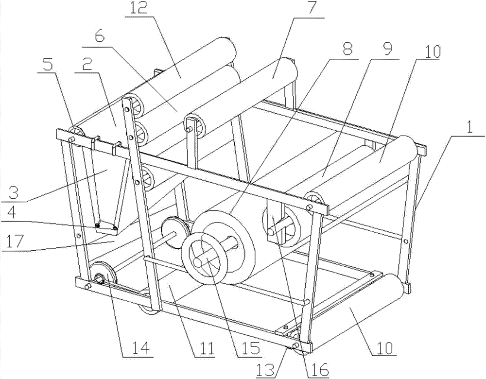
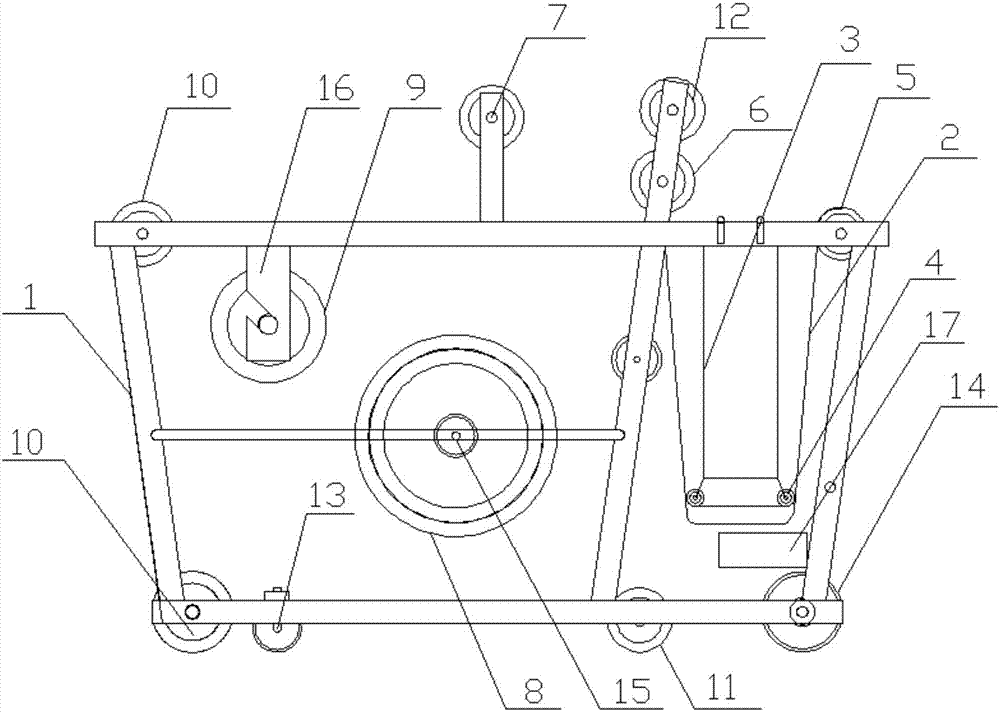
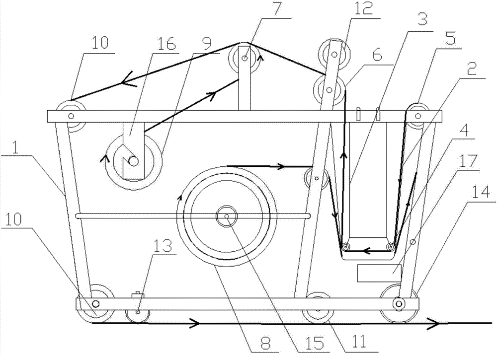
[0019] Such as Figure 1-Figure 2 As shown, the present invention discloses a waterproof on-site production and construction device, including a frame 1, an oil pan 2 and an oil immersion frame 3 are arranged on one side of the frame 1, and an oil immersion frame 3 is arranged on the The oil roller 4 and the oil immersion roller 4 are located at the bottom of the oil pan 1; the end of the frame 1 on one side of the oil pan 2 is provided with a pricking roller 5, and the frame 1 on the other side of the oil pan 2 is provided with a transmission roller 6 , The driving roller 6 is provided with a laminating roller 7; in the middle of the frame 1, below the laminating roller 7 is provided a raw material tire cloth roller 8, and the raw material tire cloth roller 8 is provided with a mask roller 9 on the frame 1 The upper and lower ends of the other side of the frame 1 are respectively provided with a steering wheel 10; under the oil pan 2 is also provided with a compaction roller 11.
[0020] The frame 1 is also provided with an oil control roller 12, the oil control roller 12 is located directly above the transmission roller 6, and a gap is reserved between the transmission roller 6 and the oil control roller 12 for the passage of the tire cloth and the mask, the oil control roller The setting of 6 is mainly to control the thickness of the oil on the tire cloth, to prevent the waste of the material caused by the laying of too thick coils and the uneven laying of the too thick coils.
[0021] A universal wheel 13 is provided at the bottom end of the front part of the frame 1, and a directional wheel 14 is provided at the bottom end of the rear part. The compaction roller 11 is arranged on both sides of the directional wheel 14. The width between the two directional wheels 14 does not exceed the width of the tire cloth, and the width of the directional wheel 14 does not exceed the width of the tire cloth. In the process of operation, the directional wheel can just press the edge of the material to make laying The coiled material does not wrinkle and does not crack at the edge.
[0022] The frame 1 has a bottom length of 1.38m, an upper length of 1.68m, a width of 1.3m, and an overall height of 1.15m.
[0023] The oil immersion rack 3 is movably arranged on the frame 1 to facilitate removal and replacement and refueling.
[0024] The raw tire cloth roller 8 is set on the frame 1 through the tire cloth reel frame 15, the tire cloth reel frame 15 is movably set on the vehicle frame 1, and the mask roll 9 is set on the vehicle frame 1 through the mask reel frame 16. Above, the facial mask shaft frame 16 is movably arranged on the frame 1.
[0025] The side section of the oil pan 2 is U-shaped, and the oil pan 2 is composed of two layers, and the middle partition is used to store the heat-conducting engine oil and to remove moisture from the tire cloth.
[0026] A power and electric device 17 is provided at the intermediate position of the directional wheel 14 and the oil pan 2 to provide power to the device.
[0027] Such as image 3 As shown, the thicker flow line in the figure is the walking trajectory of the mask, and the slightly thinner flow line is the walking trajectory of the tire cloth. It can be seen from the figure that the tire cloth is wound from the raw material tire cloth roller 8 to the bottom of the oil pan 2, so that the heat conduction oil in the oil pan compartment can remove moisture from the tire cloth, and press the oil soaking roller 4 to soak the oil. After that, it passes through the gap between the driving roller 6 and the oil control roller 12 to go out and control the oil, and then is coated by the laminating roller, driven by the steering wheel 10, and pressed by the compaction roller 11 and the orientation wheel 14 to form a waterproof layer.
[0028] At this time, the mask passes through the mask roller 9 to bypass the film roll 7 and form a whole with the tire cloth at the film roll 7 and move along the walking track of the tire cloth to complete the final roll laying.
[0029] The invention is suitable for laying various raw materials such as non-woven tyres, polyester tyres, etc., and dipping the waterproof material crude oil through the driving roller 6, after the thickness is controlled by the oil control roller 12, the film is formed by the laminating roller 7 and the steering wheel 10 is laid toward the construction base surface, and the compaction roller 11 is compacted and formed.
[0030] Its working process is as follows:
[0031] (1) First place the machine on a dry and clean construction base surface, and place the machine direction according to the construction surface.
[0032] (2) Turn the machine on, the oil pan begins to preheat, place the tire cloth on the tire cloth support, and pull it to the oil control roller; place the mask on the mask reel, and pull it to the laminating roller. Press the oil immersion roller against the tire cloth and press it into the oil pan. Add preheated hot oil to the pot. (Note: cold coating materials do not need to be heated) Adjust the thickness of the oil control roller.
[0033] (3) Pull the oiled tire cloth over the laminating roller, stick the film, pass the two turning rollers, pass under the compaction roller, and stick to the predetermined base surface.
[0034] (4) Start the machine and start construction.
[0035] The device of this patent is a revolutionary leap in the construction of existing waterproof coiled materials. (1) Compared with SBS, there is no need to brush the base oil, and no need to repeatedly pre-spread, retract and heat-melt paste. There is no need to step on it with artificial feet. Its waterproof effect can be doubled. (2) Compared with the existing self-adhesive coiled materials, there is no need for pre-laying, no bottom isolation film, less garbage after construction, medium and high temperature bonding to the base surface, no wrinkles due to temperature differences after construction, and the quality is based on the nature of the material. The physical principle changes. The effect is unparalleled. (3) Compared with the existing cold-coated type, the tire cloth is added, which overcomes the problem of pores in the cold-coated type, and does not need to be repeatedly painted.
[0036] The described embodiments are only a part of the embodiments of the present invention, rather than all the embodiments. Based on the embodiments of the present invention, all other embodiments obtained by those of ordinary skill in the art without creative work shall fall within the protection scope of the present invention.

PUM

no PUM

Description & Claims & Application Information

We can also present the details of the Description, Claims and Application information to help users get a comprehensive understanding of the technical details of the patent, such as background art, summary of invention, brief description of drawings, description of embodiments, and other original content. On the other hand, users can also determine the specific scope of protection of the technology through the list of claims; as well as understand the changes in the life cycle of the technology with the presentation of the patent timeline. Login to view more.

Similar technology patents

Anti-sagging polyurethane-modified asphalt waterproof adhesive coating for side wall

ActiveCN112341886AImprove waterproof effectGood waterproof effectBituminous coatingsBituminous waterproofingAntifoam agent
Owner:北京金盾建材有限公司

Double-layer lining shield tunnel deformation joint structure and shield tunnel

PendingCN108150192AReduce the amount of openingImprove waterproof effectUnderground chambersTunnel liningTransverse shearEngineering
Owner:CHINA RAILWAY SIYUAN SURVEY & DESIGN GRP

Classification and recommendation of technical efficacy words

  • Improve waterproof effect
  • Reduce waste

Variable Compliance Wheel

ActiveUS20110272254A1Improve lateral performanceReduce wasteShaft and bearingsNon-inflatable tyresEngineeringMechanical engineering
Owner:MILLENWORKS
Why Eureka
Try Eureka