
Damping device for steel structure bridge building

A shock absorbing device and steel structure technology, which is applied in the field of bridge construction, can solve the problems of life-threatening pedestrians, high maintenance costs, and complicated manufacturing processes, and achieve the effects of high shock absorbing efficiency, convenient maintenance, and convenient use

Inactive Publication Date: 2017-11-24
沈利丹
View PDF0 Cites 5 Cited by
  • Summary
  • Abstract
  • Description
  • Claims
  • Application Information

AI Technical Summary

Problems solved by technology

[0003] In the vast land of our country, there are many large and small rivers, which need to build steel structure bridges. In the cities that are constantly being planned, more and more pedestrian bridges and overpasses are built. When the seismic performance of steel structure bridges When it is not strong, relative displacement will occur between many structures of the steel structure bridge. When the displacement exceeds the limit, the steel structure bridge will be damaged, posing a threat to the lives of pedestrians. A problem that must be paid attention to when building bridges. Most of the existing steel structure bridge shock absorbers are dampers that provide movement resistance to reduce vibration and energy dissipation.
The disadvantages of this kind of damper are: the manufacturing process is complicated, the cost is high, the maintenance cost is high, and the use cost is high, so it is not suitable for popularization and use.

Method used


Image

  • Damping device for steel structure bridge building
  • Damping device for steel structure bridge building
  • Damping device for steel structure bridge building

Examples


Embodiment Construction

[0021] The technical solution of this patent will be further described in detail below in conjunction with specific embodiments.

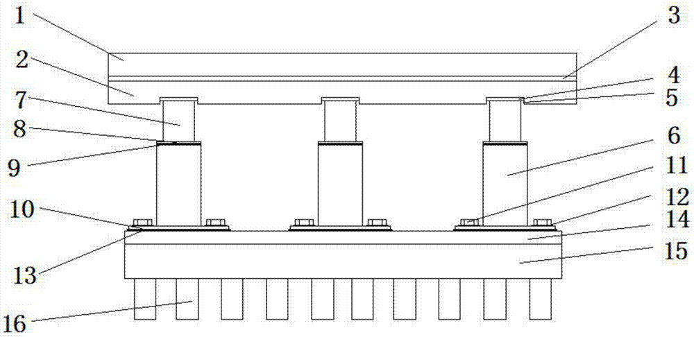
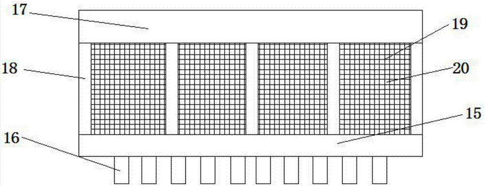
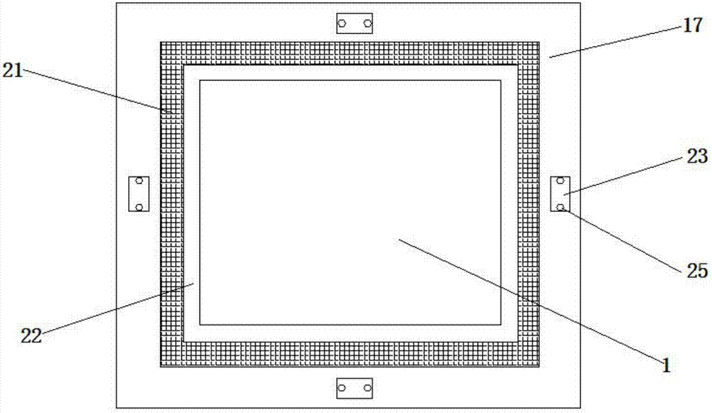
[0022] see Figure 1-5 , a steel structure bridge building shock absorber, comprising a pressure bearing plate 1 and a cement base 15; the lower surface of the pressure bearing plate 1 is provided with a shock absorbing pad 3; the bottom of the shock absorbing pad 3 is provided with an upper rubber block 2 The lower surface of the upper rubber block 2 is provided with a plurality of grooves 5; the buffer block 4 is provided in the groove 5; the buffer block 4 is fixedly connected with the upper rubber plate 2, and the buffer block 4 is provided below There are notches; a plurality of stabilizing posts 16 are arranged under the cement base 15; a lower rubber block 14 is arranged on the upper surface of the cement base 15; a plurality of decompression pads 13 are installed on the lower rubber block 14; A base 10 is placed on the decompression pad 13...


PUM


Abstract

The invention discloses a shock absorbing device for a steel structure bridge building, which comprises a pressure bearing plate and a cement base; it is characterized in that a shock absorbing pad is provided on the lower surface of the pressure bearing plate; block; the lower surface of the upper rubber block is provided with a plurality of grooves; the groove is provided with a buffer block; the bottom of the cement base is provided with a plurality of stabilizing posts; the upper surface of the cement base is provided with a lower rubber block; the lower rubber block is provided with a plurality of decompression pads; the decompression pad is provided with a base; the base is provided with a first screw and a cylinder column; the first screw and the base A plug pad is provided between them; a buffer pad is provided at the top of the cylinder column; a friction block is provided on the buffer pad; a telescopic column is provided at the hollow inside the cylinder column; an elastic column is provided between the telescopic column and the bottom of the cylinder column. blocks; multiple load-bearing columns are fixedly installed on the edge of the upper surface of the cement base; the invention has a simple structure, and can reduce the longitudinal vibration of the pier through the telescopic columns and the cylinder columns.

Description

technical field [0001] The invention relates to the technical field of bridge construction, in particular to a steel structure bridge construction damping device. Background technique [0002] Bridges generally refer to structures erected on rivers, lakes and seas to allow vehicles and pedestrians to pass smoothly. In order to adapt to the modern high-speed development of the transportation industry, bridges are also extended to buildings that cross mountain streams, poor geology or meet other transportation needs to make traffic more convenient. A bridge is generally composed of a superstructure, a substructure, a support and ancillary structures. The superstructure is also called a bridge span structure, which is the main structure for crossing obstacles; the substructure includes abutments, piers and foundations; Or the force transmission device set at the supporting place of the abutment; the auxiliary structures refer to the bridge head plate, conical slope protection,...

Claims


Application Information

Patent Timeline
IPC IPC(8): E01D19/00E01D19/04
CPCE01D19/00E01D19/04
Inventor 沈利丹沈佳佳
Owner 沈利丹
Learn More