Backlight luminosity and heat dissipation detection device

A testing equipment and backlight technology, which is applied in the testing of optical instruments, measuring devices, and testing of machine/structural components, etc., can solve the problems of large error in testing results, inability to observe internal conditions, slow heat dissipation, etc. The effect of detection error, improved detection accuracy and high airtightness

Inactive Publication Date: 2017-11-24
YANCHENG SANDING ELECTRONICS TECH CO LTD
View PDF0 Cites 2 Cited by
  • Summary
  • Abstract
  • Description
  • Claims
  • Application Information

AI Technical Summary

Problems solved by technology

[0002] As we all know, the detection equipment for backlight emission and heat dissipation is an auxiliary device used in the production process of backlight to detect the heat dissipation when it emits light, so that the staff can better understand and analyze multiple groups of backlight. It has been widely used in the field of backlight production; the existing backlight luminous radiation detection equipment includes a work box, a detector and four sets of brackets. There is a working chamber inside the work box, and a pick-and-place opening is provided on the top of the work box. , and a cover is set at the pick-and-place opening. The tops of the four sets of brackets are respectively installed on the left front side, right front side, left rear side and right rear side of the bottom of the work box. The detector is installed on the top of the cover. Pass through the cover and extend into the inside of the working cavity; when the existing backlight luminous heat dissipation detection equipment is used, the luminous backlight is placed in the working cavity, and the heat dissipation is detected by the detector; the existing backlight During the use of the source luminescence heat dissipation detection equipment, it was found that the heat dissipation speed of the work box was slow after the test, resulting in poor practicability; and when the work box was tested, the internal conditions could not be observed, resulting in poor reliability; and the luminescence When the backlight source is placed, the contact area with the working chamber is large, which leads to a large error in the detection result

Method used


Image

  • Backlight luminosity and heat dissipation detection device
  • Backlight luminosity and heat dissipation detection device
  • Backlight luminosity and heat dissipation detection device

Examples


Embodiment Construction

[0014] The specific implementation manners of the present invention will be further described in detail below in conjunction with the accompanying drawings and embodiments. The following examples are used to illustrate the present invention, but are not intended to limit the scope of the present invention.

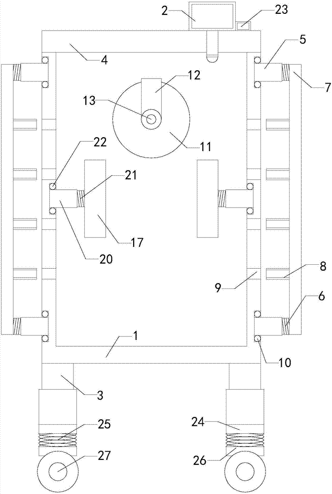
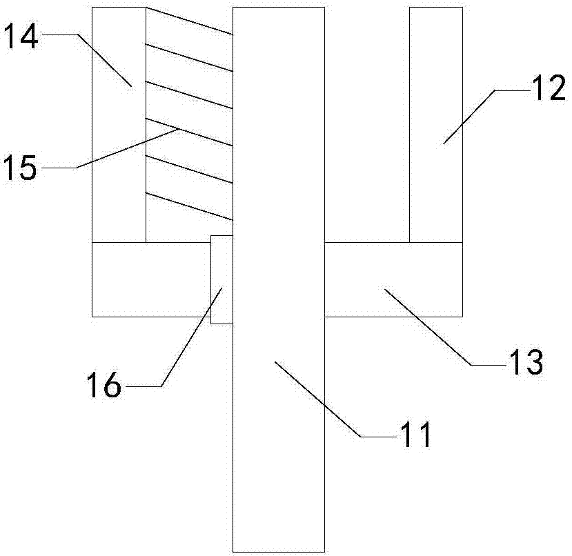
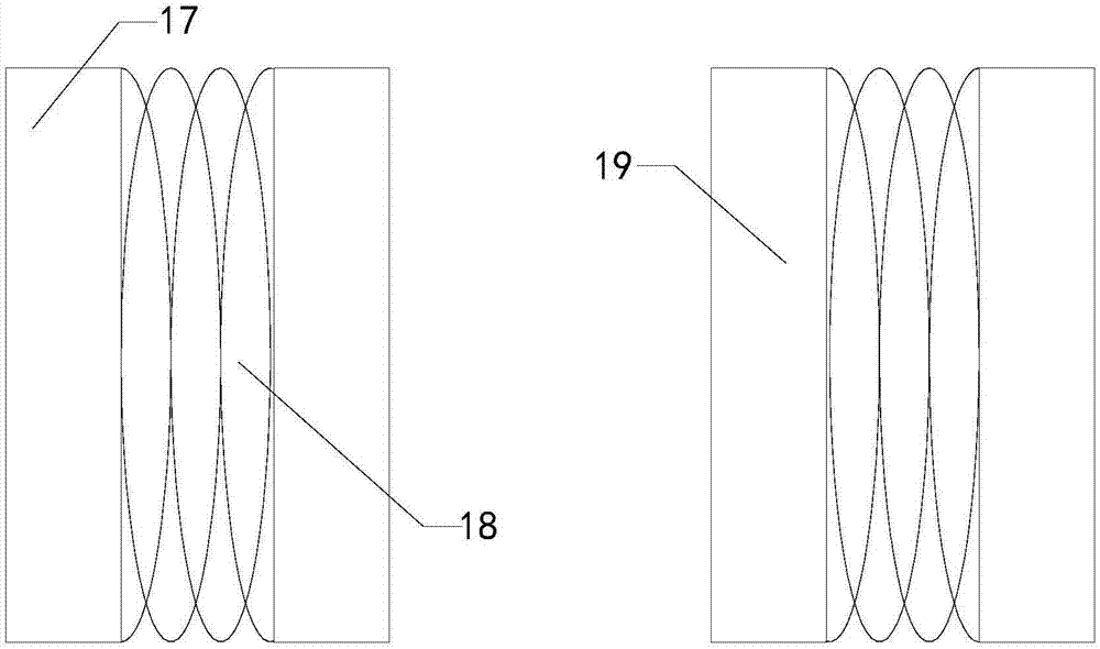
[0015] Such as Figure 1 to Figure 3 As shown, a kind of backlight luminous heat radiation detection equipment of the present invention comprises a working box 1, a detector 2 and four sets of supports 3, a working chamber is arranged inside the working box, and a pick-and-place opening is arranged on the top of the working box, and A cover 4 is provided at the access opening, and the tops of the four sets of brackets are respectively installed on the left front, right front, left rear and right rear of the bottom of the work box. The cover extends into the working chamber; it also includes two sets of first left-threaded tubes, two sets of first left-threaded rods, a lef...


PUM


Abstract

The present invention relates to the technical field of backlight detection accessory devices, in particular to a backlight luminous radiation detection device, which has a faster heat dissipation speed after the detection of the work box, which improves its practicability; and when the work box is detected, the internal The situation can be observed to improve its reliability; and when the luminous backlight is placed, the contact area with the working chamber is reduced, thereby reducing the error of the detection result; it includes the work box, the detector and four sets of brackets; it also includes two sets of first left Threaded pipe, two sets of first left threaded rods, left support plate, multiple sets of left blocking blocks, two sets of first right threaded pipes, two sets of first right threaded rods, right support plate and multiple sets of right blocking blocks; at the observation hole It is equipped with a transparent baffle, and also includes handles, rotating shafts, driving shafts, bristles and sealing rings; it also includes two sets of left connecting plates, two sets of left connecting springs, two sets of left clamping plates, two sets of right connecting plates, and two sets of right connecting plates. Spring and two sets of right pallets.

Description

technical field [0001] The invention relates to the technical field of backlight detection accessory devices, in particular to a detection device for backlight radiance and heat dissipation. Background technique [0002] As we all know, the detection equipment for backlight emission and heat dissipation is an auxiliary device used in the production process of backlight to detect the heat dissipation when it emits light, so that the staff can better understand and analyze multiple groups of backlight. It has been widely used in the field of backlight production; the existing backlight luminous radiation detection equipment includes a work box, a detector and four sets of brackets. There is a working chamber inside the work box, and a pick-and-place opening is provided on the top of the work box. , and a cover is set at the pick-and-place opening. The tops of the four sets of brackets are respectively installed on the left front side, right front side, left rear side and right...

Claims


Application Information

Patent Timeline
Patent Type & Authority Applications(China)
IPC IPC(8): G01M11/00
CPCG01M11/00
Inventor 赵圣铭李彦龙
Owner YANCHENG SANDING ELECTRONICS TECH CO LTD
Why Eureka
Try Eureka