
Test system for electronic device false triggering under strong electromagnetic radiation by applying optical fiber communication

An electronic device and optical fiber communication technology, which is applied in the field of test systems, can solve problems affecting the accuracy of experimental results and interference of transmitted electrical signals, and achieve the effects of convenient display of experimental results, reduction of interference, and low cost

Inactive Publication Date: 2017-11-24
NANJING UNIV OF SCI & TECH
View PDF6 Cites 3 Cited by
  • Summary
  • Abstract
  • Description
  • Claims
  • Application Information

AI Technical Summary

Problems solved by technology

[0005] The technical problem to be solved by the present invention is to provide a test system that uses optical fiber communication to trigger false triggers of electronic devices under strong electromagnetic radiation, so as to solve the problem that ordinary metal wires are prone to interference and even affect the accuracy of experimental results when transmitting electrical signals in a strong electromagnetic radiation environment. The problem

Method used


Image

  • Test system for electronic device false triggering under strong electromagnetic radiation by applying optical fiber communication
  • Test system for electronic device false triggering under strong electromagnetic radiation by applying optical fiber communication

Examples


Embodiment Construction

[0024] In order to illustrate the technical scheme and technical purpose of the present invention, the present invention will be further introduced below in conjunction with the accompanying drawings and specific embodiments.

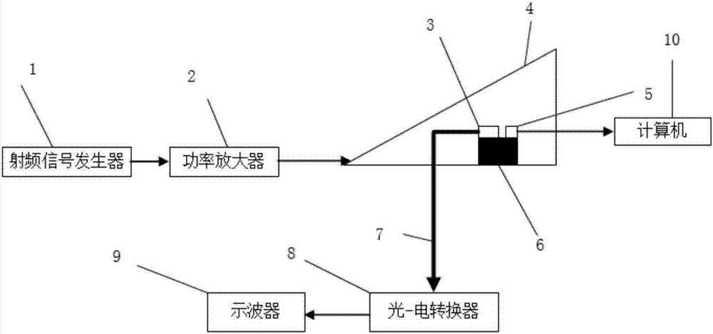
[0025] combine figure 1 , a test system for false triggering of electronic devices using optical fiber communication under strong electromagnetic radiation of the present invention, comprising a radio frequency signal generator 1, a power amplifier 2, an electrical-optical signal converter 3, a GTEM chamber 4, and a field strength tester 5 , base platform 6, optical fiber 7, optical-electrical signal converter 8, oscilloscope 9, computer 10;

[0026] The radio frequency signal generator 1 is used to generate a radio frequency signal, which is amplified by the power amplifier 2 and transmitted to the GTEM cell 4, and the intensity of the electromagnetic field in the GTEM cell 4 is adjusted by adjusting the radio frequency signal.

[0027] The input end ...


PUM


Abstract

The invention discloses a test system for electronic device false triggering under strong electromagnetic radiation by applying optical fiber communication, which comprises a radio frequency signal generator, a power amplifier, a GTEM cell, an electric-optical signal converter, a field strength tester, an optical fiber, an optical-electric signal converter and an oscilloscope, wherein the radio frequency signal generator generates radio frequency electric signals; the power amplifier amplifies the radio frequency signals; the GTEM cell uses the amplified radio frequency signals to excite a uniform high-frequency strong electric field around a core board; the electric-optical signal converter is used for converting false triggering electric signals generated by a tested electronic device due to radiation interference to optical signals not disturbed by the radiation interference; the optical signals are transmitted to the optical-electric converter outside the cell through the optical fiber and are converted to electric signals; and finally, the false triggering electric signals are displayed by the oscilloscope. Complete transmission of the electric signals with no interference in the strong electromagnetic radiation environment can be realized, and the system has the advantages of shielding outer interference and isolating pollution on the outside by the self electromagnetic field.

Description

technical field [0001] The invention belongs to the technical field of test and measurement, in particular to a test system for false triggering of electronic devices under strong electromagnetic radiation using optical fiber communication. Background technique [0002] With the rapid development and wide application of electronic and electrical technologies such as electronic computers, information technology, testing technology, and semiconductors, there are more and more electronic devices in life and work, and the electromagnetic environment is becoming increasingly harsh, which requires higher electromagnetic compatibility for electronic products. In general, the performance of the electronic device will determine the degree of electromagnetic compatibility of the terminal product, especially in the high frequency band, the electronic device itself may be a source of interference or a sensitive part, which will bring a lot of electromagnetic compatibility problems. How ...

Claims


Application Information

Patent Timeline
Patent Type & Authority Applications(China)
IPC IPC(8): G01R31/00G01R29/08G08C23/06
CPCG01R29/0814G01R29/0871G01R31/003G08C23/06
Inventor 王陶蓉黄学功
Owner NANJING UNIV OF SCI & TECH
Learn More