A multi-rotor UAV optical flow hovering method based on imu attitude compensation

A multi-rotor UAV, UAV technology, applied in attitude control, photo interpretation, image enhancement and other directions, can solve problems such as inability to hover accurately, poor real-time performance, poor environmental adaptability, etc., to ensure accuracy, guarantee Real-time performance, the effect of controlling the amount of calculation

Active Publication Date: 2020-12-04
西安因诺航空科技有限公司
View PDF2 Cites 0 Cited by
  • Summary
  • Abstract
  • Description
  • Claims
  • Application Information

AI Technical Summary

Problems solved by technology

[0008] The purpose of the present invention is to provide a multi-rotor UAV optical flow hovering method based on IMU attitude compensation, which solves the problem that the existing UAV cannot hover accurately in outdoor or indoor scenes with weak GPS signals, and the Poor environmental adaptability and poor real-time performance

Method used


Image

  • A multi-rotor UAV optical flow hovering method based on imu attitude compensation
  • A multi-rotor UAV optical flow hovering method based on imu attitude compensation
  • A multi-rotor UAV optical flow hovering method based on imu attitude compensation

Examples


Embodiment Construction

[0036] The present invention will be described in detail below in conjunction with the accompanying drawings and specific embodiments.

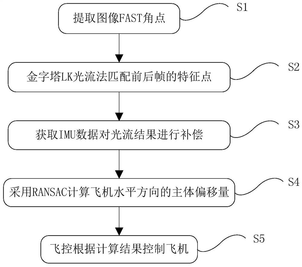
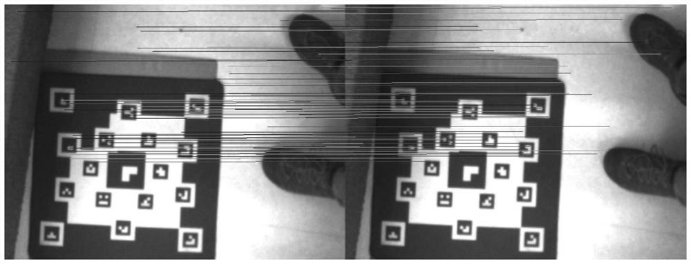
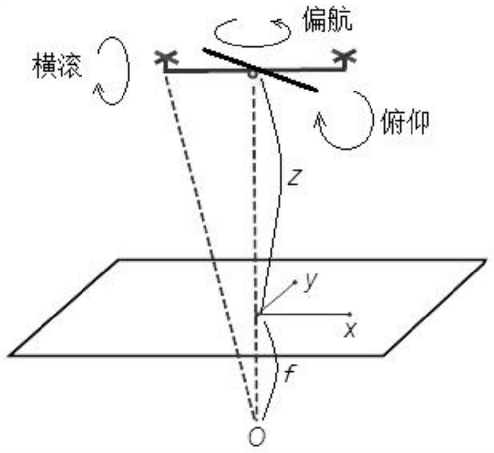
[0037] as attached figure 1 As shown, the present invention provides a multi-rotor UAV optical flow hovering method based on IMU attitude compensation. First, extract FAST corner points from all image frames captured by the optical flow camera; then use the pyramid LK optical flow method to match the front and rear frames Extracted FAST corner points, and establish feature point pairs, and then obtain the optical flow structure of the front and rear image frames through the feature point pairs; then use the obtained IMU data to compensate the optical flow results; then use the RANSAC random sampling consistency method Calculate the main body offset in the horizontal direction of the aircraft; finally send the calculation result to the flight control device to keep the aircraft hovering.

[0038] The concrete implementation steps of described...


PUM


Abstract

An IMU attitude compensation-based multi-rotor unmanned aerial vehicle optical flow hovering method provided by the present invention adds the IMU attitude compensation on the basis of an optical flow result, thereby guaranteeing the unmanned aerial vehicle actual hovering accuracy very well. By adopting the FAST angular points as a feature point extraction method, the IMU attitude compensation-based multi-rotor unmanned aerial vehicle optical flow hovering method can be suitable for an environment that is relatively weaker in textures, and does not need to depend on any priori knowledge, thereby improving the adaptability of an unmanned aerial vehicle very well. By taking an optical flow method as the basis, the IMU attitude compensation-based multi-rotor unmanned aerial vehicle optical flow hovering method controls the calculation amount effectively under the premise of guaranteeing the precision, thereby guaranteeing the real-time performance of an algorithm, and realizing the actual processing speed that can reach 50 Hz on an embedded system.

Description

technical field [0001] The invention belongs to the technical field of unmanned aerial vehicle visual navigation, and in particular relates to an optical flow hovering method of a multi-rotor unmanned aerial vehicle based on IMU attitude compensation. Background technique [0002] As drones gradually enter people's lives, there are more and more applications based on drone platforms, especially the introduction of the vision system, which not only greatly reduces the user threshold, improves flight safety, but also greatly enriches the user experience. Experience, bring more fun to flight. Hover positioning is an important feature that distinguishes multi-rotor UAVs from fixed-wing UAVs. It has broad application prospects in fixed-point shooting and power line inspection, especially when the outdoor GPS signal is weak or there is no GPS signal indoors. , it is particularly important to ensure that the drone hovers stably at the designated position. [0003] At present, the...

Claims


Application Information

Patent Timeline
Patent Type & Authority Patents(China)
IPC IPC(8): G05D1/04G05D1/08G01C21/16G01C11/08G06T7/246G06T7/269G06T7/13G06T7/77
CPCG01C11/08G01C21/165G05D1/042G05D1/0825G06T2207/20164G06T7/13G06T7/248G06T7/269G06T7/77
Inventor 雍旭东闫志敏
Owner 西安因诺航空科技有限公司
Why Eureka
Try Eureka