Method for manufacturing chip mounting substrate and chip mounting substrate

A chip mounting and substrate technology, which is used in semiconductor/solid-state device manufacturing, semiconductor/solid-state device parts, semiconductor devices, etc. The effect of reducing bonding force and manufacturing cost

Active Publication Date: 2020-04-24
POINT ENG
View PDF4 Cites 0 Cited by
  • Summary
  • Abstract
  • Description
  • Claims
  • Application Information

AI Technical Summary

Problems solved by technology

[0008] However, in the method of using a mask in this way, there is a problem that a separate mask is required
Further, when the bump 130 is formed on the metal substrate having the cavity 140, there is a problem of lowered precision using a planar mask.
In addition, it is difficult to manufacture a mask curved in a shape corresponding to the shape of the cavity 140 having a small size

Method used


Image

  • Method for manufacturing chip mounting substrate and chip mounting substrate
  • Method for manufacturing chip mounting substrate and chip mounting substrate
  • Method for manufacturing chip mounting substrate and chip mounting substrate

Examples


Embodiment Construction

[0045] Embodiments of the present invention will now be described in detail with reference to the accompanying drawings.

[0046] For the same structure of the present invention as the prior art, reference is made to the prior art. A detailed description thereof will be omitted.

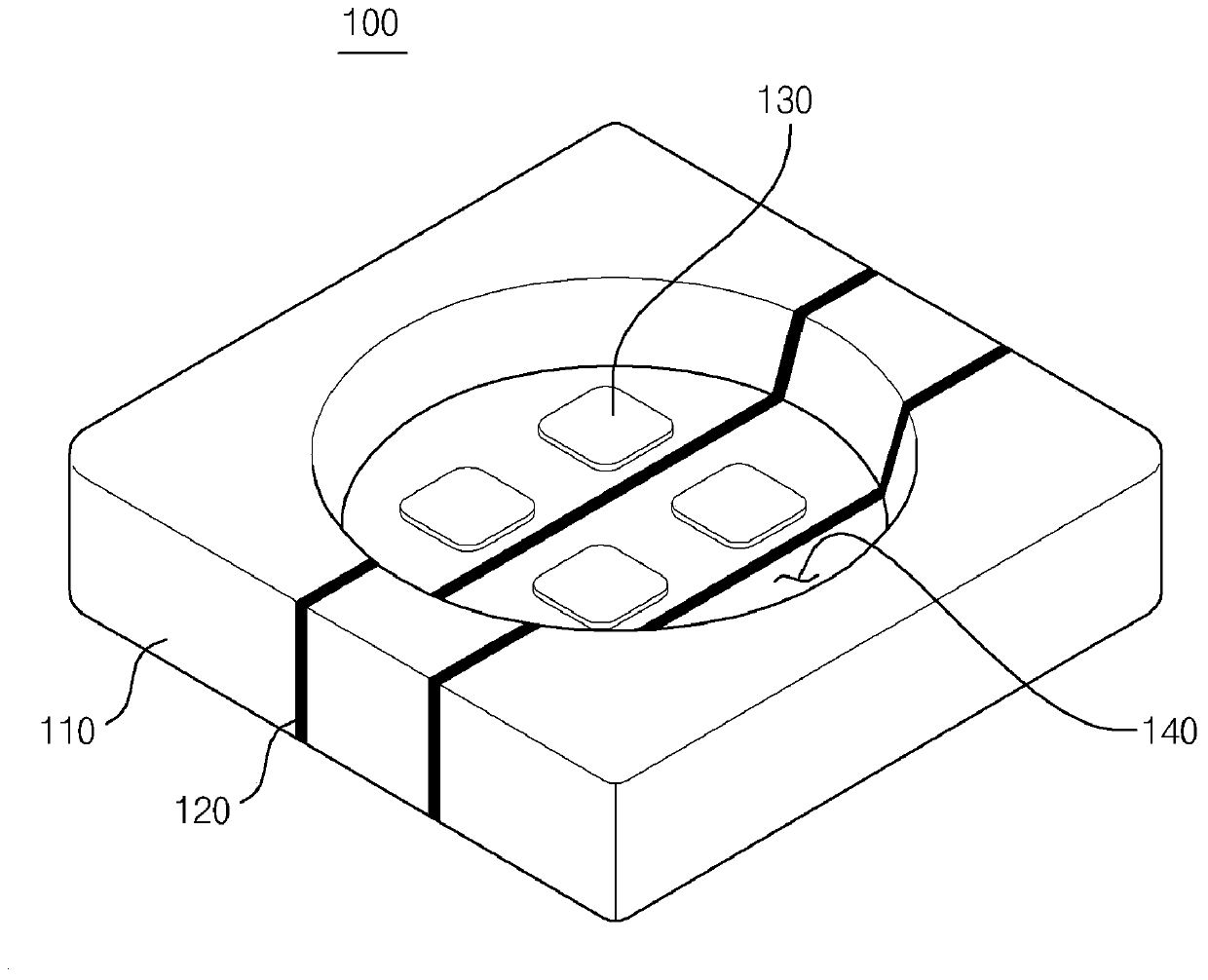
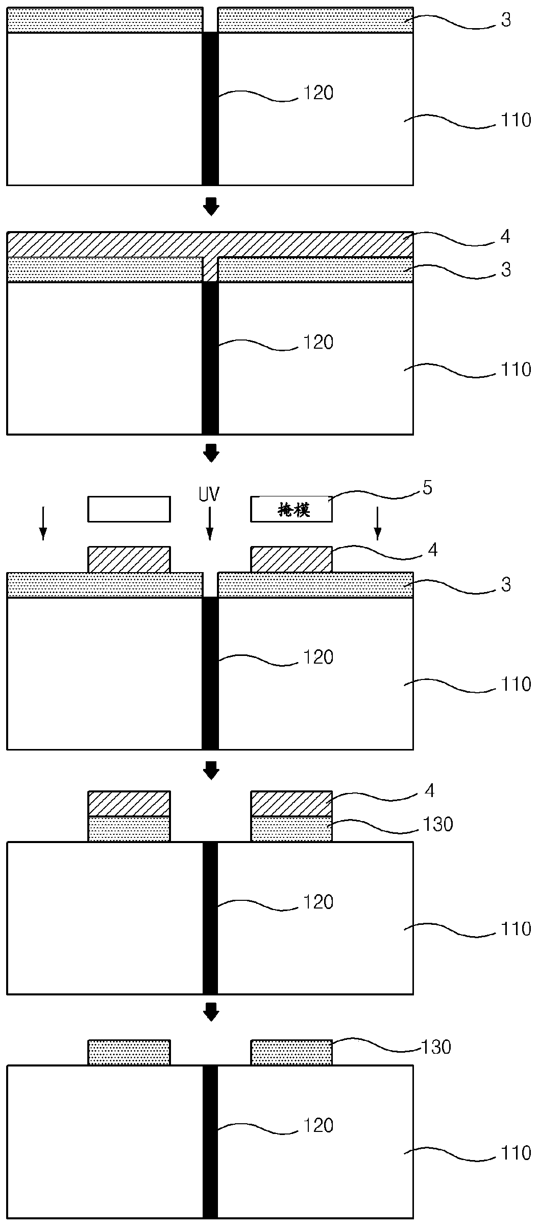
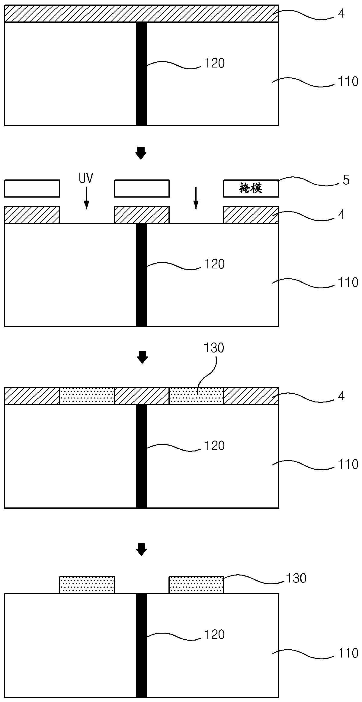
[0047] refer to Figure 4 , according to the manufacturing method of the chip mounting substrate of the embodiment of the present invention, comprise: the pre-coating step that forms pre-coating layer 60 on the metal substrate 10 that is divided into two conductive parts by insulating part 20; ) an etching step of etching at least a part of the precoat layer 60 to form a pattern 50; and a step of forming the metal layer 30 on the metal substrate 10, wherein the pattern 50 is provided on at least one of the two conductive portions divided by the insulating portion 20 , and the metal layer 30 is formed in the pattern 50 .

[0048] The method of this embodiment may further include a cavity forming st...


PUM


Abstract

A method of manufacturing a chip mounting substrate, the method comprising a precoating step, an etching step and a step of forming a metal layer on the substrate, the precoating step forming a precoat on the substrate, the substrate comprising a plurality of conductor parts and interposed conductive parts The insulating portion between the portions, the etching step etches at least a portion of the precoat layer by a laser to form a pattern. A pattern is provided on the at least one conductive portion, and a metal layer is formed in the pattern.

Description

technical field [0001] The present invention relates to a method for manufacturing a chip mounting substrate, and more particularly, to a method for manufacturing a chip mounting substrate, the method including an etching step and a step of forming a metal layer in a pattern, the etching step is performed by a laser At least a portion of the precoat is etched to form a pattern. Background technique [0002] In general, light emitting diodes (LEDs), which are semiconductor light emitting diodes, are environmentally friendly light sources that do not cause pollution. Light-emitting diodes have drawn attention from all sides. In recent years, as the use of LEDs has expanded to various fields such as indoor / outdoor lighting, automotive headlights, and backlight units (BLUs) of display devices, high luminous efficiency and excellent heat dissipation characteristics have been required to be achieved. In order to obtain high-efficiency LEDs, it is necessary to mainly improve the ...

Claims


Application Information

Patent Timeline
Patent Type & Authority Patents(China)
IPC IPC(8): H01L33/48H01L33/62
CPCH01L33/486H01L33/62H01L2933/0066H01L21/481H01L21/4846H01L33/46H01L33/60H01L2224/81385H01L2224/83385H01L2224/83439H01L2224/85439H01L23/498H01L23/00H01L2924/15153H01L33/005H01L33/02H01L33/22H01L33/44H01L2924/12041H01L2933/0025H01L2933/0033
Inventor 安范模朴胜浩宋台焕
Owner POINT ENG
Why Eureka
Try Eureka