
Rotational inerter and method for damping an actuator

A technology for actuators and inerters, applied in the field of rotary inerters, can solve problems such as reducing aircraft safety, increasing aircraft aerodynamic resistance, and increasing weight

Active Publication Date: 2017-11-28
THE BOEING CO
View PDF24 Cites 6 Cited by
  • Summary
  • Abstract
  • Description
  • Claims
  • Application Information

AI Technical Summary

Problems solved by technology

The increased size of the actuator can protrude further beyond the outer mold line of the aerodynamic surface, resulting in an increase in the aerodynamic drag of the aircraft
Reduced attitude controllability, increased weight, and increased aerodynamic drag of the hydraulic system can reduce the safety, fuel efficiency, range, and / or payload capacity of the aircraft

Method used


Image

  • Rotational inerter and method for damping an actuator
  • Rotational inerter and method for damping an actuator
  • Rotational inerter and method for damping an actuator

Examples


Embodiment Construction

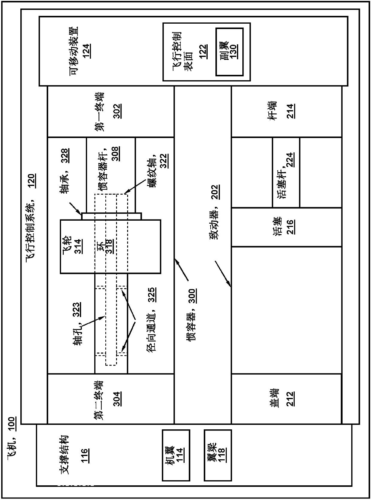
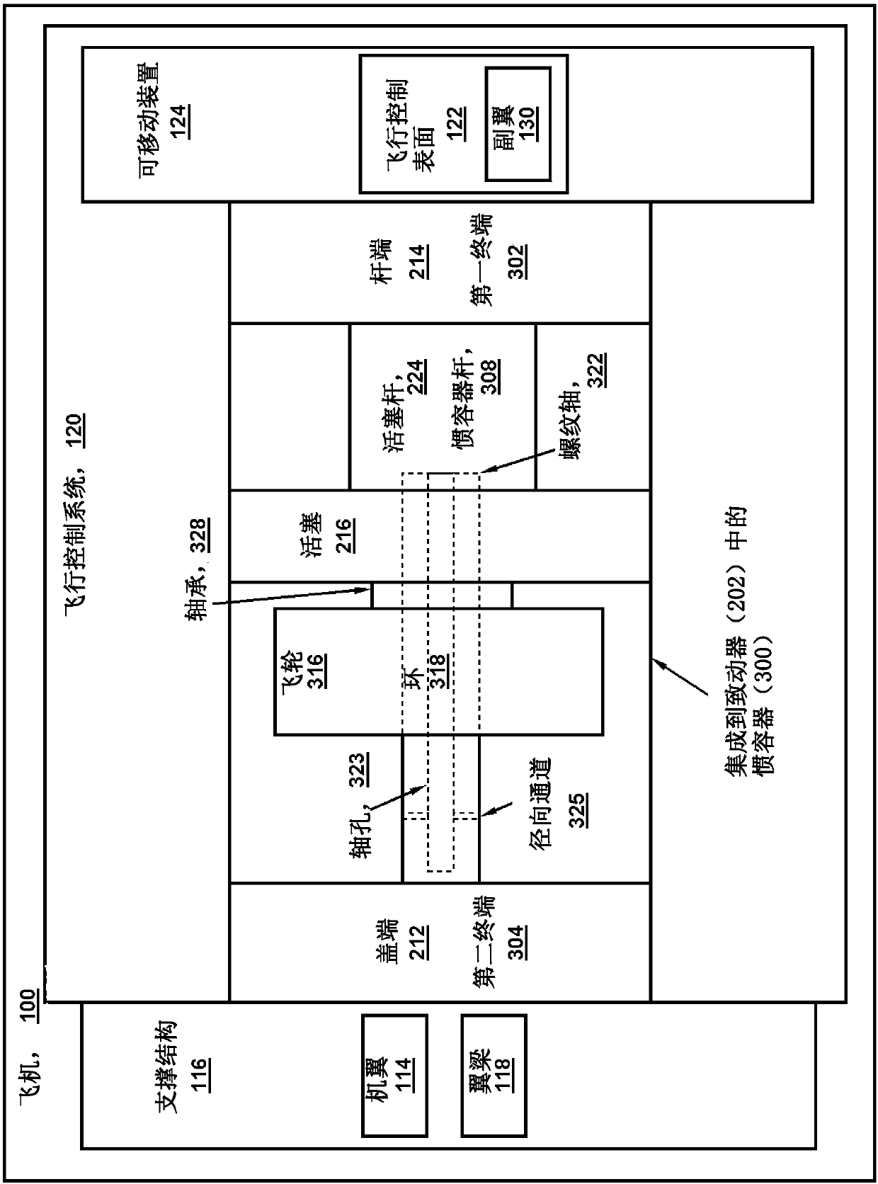
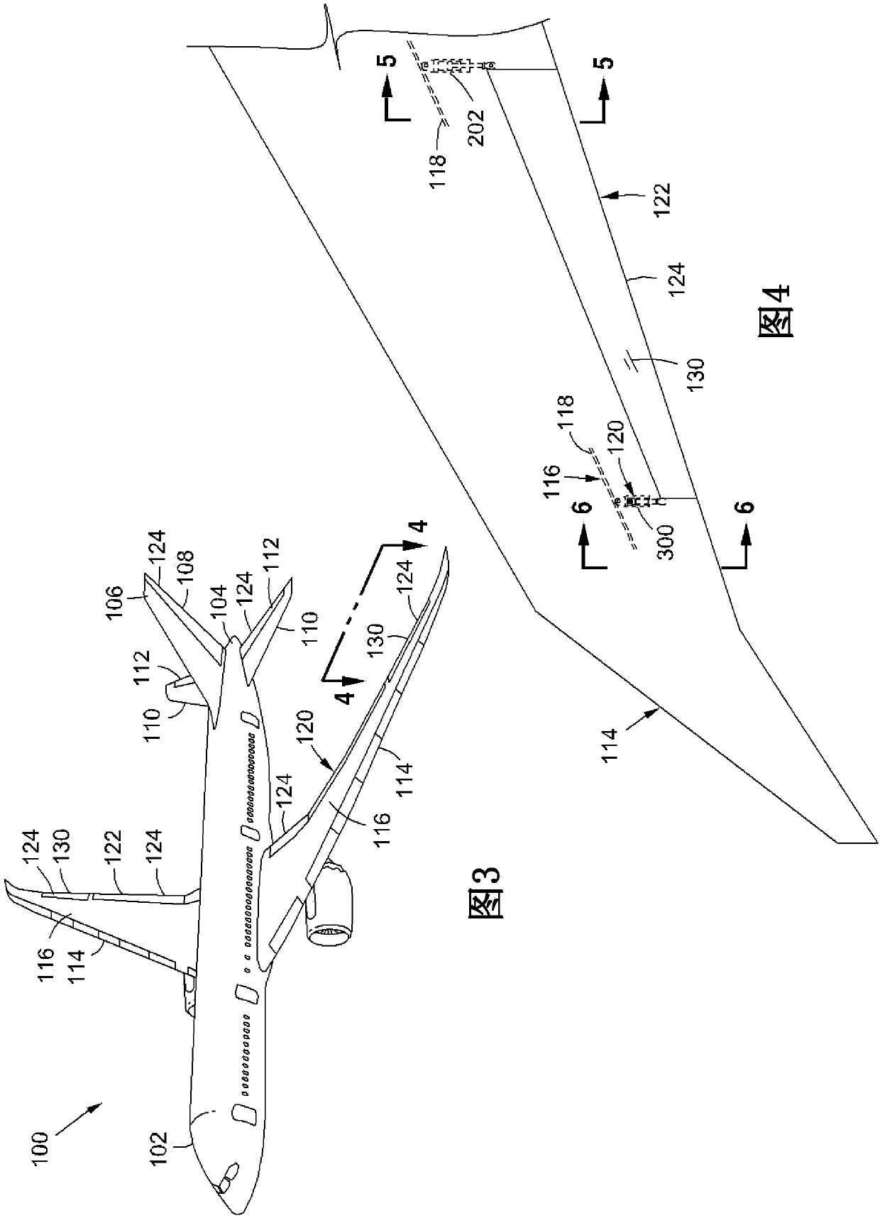
[0035]Referring now to the drawings, in which the drawings are shown for purposes of illustrating various examples of the present disclosure, figure 1 Shown is a block diagram of hydraulic actuator 204 coupled between support structure 116 and movable device 124 and configured to move or actuate movable device 124 . The block diagram advantageously includes an inerter 300 for damping rotation of the actuator 202 . Inerter vessel 300 is shown coupled between support structure 116 and movable device 124 and is configured to improve the dynamic response of movable device 124 during actuation by actuator 202 , as described in more detail below. exist figure 1 and Figure 4-Figure 9 In the example shown, the inerter vessel 300 is provided as a separate component from the actuator 202 . However, other examples described below (eg, figure 2 and Figure 10-Figure 21 ), the container 300 is integrated into the actuator 202.

[0036] Actuator 202 includes a piston 216 coupled to ...


PUM


Abstract

An apparatus for damping an actuator includes an inerter. The inerter includes a first terminal and a second terminal movable relative to one another along an inerter axis and configured to be mutually exclusively coupled to a support structure and a movable device actuated by an actuator. The inerter further includes a rod coupled to and movable with the first terminal and a threaded shaft coupled to and movable with the second terminal. The inerter further includes a flywheel having a flywheel annulus coupled to one of the rod and the threaded shaft. The flywheel is configured to rotate in proportion to axial acceleration of the rod relative to the threaded shaft in correspondence with actuation of the movable device by the actuator.

Description

technical field [0001] The present disclosure relates to actuators, and more particularly to rotary inertial vessels and methods for damping actuators. Background technique [0002] Aircraft typically include a flight control system for directional and attitude control of the aircraft in response to commands from the flight crew or an autopilot. The flight control system may include multiple movable flight control surfaces such as ailerons on the wings for roll control, elevators on the horizontal tail of the tail for pitch control, vertical tails for yaw control Rudder and other movable control surfaces on the tail. Movement of the flight control surfaces is typically accomplished by one or more actuators mechanically coupled between the support structure (eg, spar) and the flight control surface (eg, ailerons). In many aircraft, actuators for flight control surfaces are linear hydraulic actuators driven by one or more hydraulic systems, usually operating at a fixed opera...

Claims


Application Information

Patent Timeline
Patent Type & Authority Applications(China)
IPC IPC(8): B64C9/00
CPCB64C9/00F16F7/1022F16F2232/06F15B15/088F15B15/22F15B15/227F15B2015/206B64C13/40Y02T50/40F15B15/14F15B15/02F16F7/1011F16F7/1028F16F15/02F16F2222/08F16F2232/02
Inventor M·T·福克斯J·M·罗奇
Owner THE BOEING CO
Learn More