Drying device for wood boards for furniture

A drying device and wood board technology, which is applied in drying, dryers, heating devices, etc., can solve the problems of high labor intensity for operators, low drying quality of wood boards, and low drying uniformity, so as to improve the drying efficiency. Dry uniformity, reduce labor intensity, enhance the effect of wood board quality

Inactive Publication Date: 2017-11-28
李琪
View PDF7 Cites 13 Cited by
  • Summary
  • Abstract
  • Description
  • Claims
  • Application Information

AI Technical Summary

Problems solved by technology

[0003] The purpose of the present invention is to overcome the problems of low drying quality of wood boards, low drying uniformity, high labor intensity of operators and low work efficiency existing in the existing wood board drying device, and to provide a wood board drying device with reasonable structure design and high drying efficiency. Drying device for wooden boards for furniture with high quality, good drying quality and low labor intensity for operators

Method used


Image

  • Drying device for wood boards for furniture
  • Drying device for wood boards for furniture
  • Drying device for wood boards for furniture

Examples


Embodiment 1

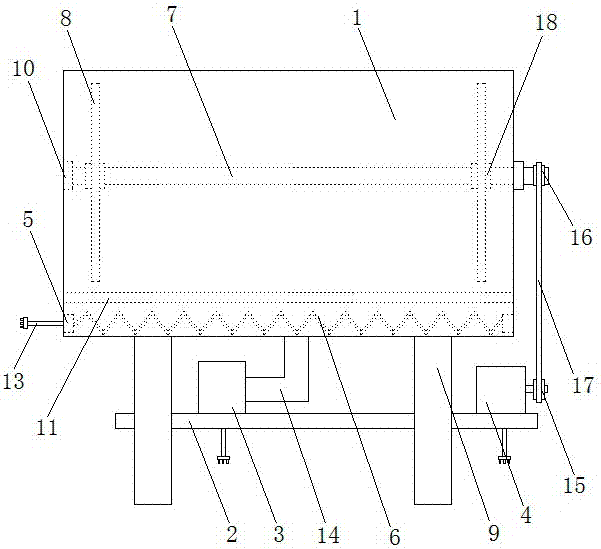
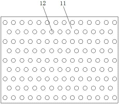
[0018] as attached Figure 1-3 As shown, a drying device for wood boards for furniture, comprising a drying cylinder 1, a fixed plate 2, a blower 3, a motor 4, a heating block 5, a heating wire 6, a rotating shaft 7 and a bearing plate 8, is characterized in that: The drying cylinder 1 is arranged on the bracket 9, the bearing 10 is arranged on the drying cylinder 1, and the baffle plate 11 is arranged in the drying cylinder 1, and the fixing plate 2 is arranged between the bracket 9 and the bracket 9. Between, the blower 3 is set on the fixed plate 2, and the blower 3 is provided with a power cord 13, the air inlet pipe 14, the motor 4 is set on the fixed plate 2, and the motor 4 is provided with a power supply Wire 13, driving wheel 15, the heating block 6 is arranged in the drying cylinder 1, and a power line 13 is arranged on the heating block 5, and the heating wire 6 is arranged between the heating block 5 and the heating block 5 One end of the rotating shaft 7 is set i...

Embodiment 2

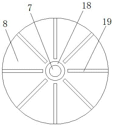
[0024] as attached Figure 4 As shown, a drying device for wood boards for furniture, comprising a drying cylinder 1, a fixed plate 2, a blower 3, a motor 4, a heating block 5, a heating wire 6, a rotating shaft 7 and a bearing plate 8, is characterized in that: The drying cylinder 1 is arranged on the bracket 9, the bearing 10 is arranged on the drying cylinder 1, and the baffle plate 11 is arranged in the drying cylinder 1, and the fixing plate 2 is arranged between the bracket 9 and the bracket 9. Between, the blower 3 is set on the fixed plate 2, and the blower 3 is provided with a power cord 13, the air inlet pipe 14, the motor 4 is set on the fixed plate 2, and the motor 4 is provided with a power supply Wire 13, driving wheel 15, the heating block 6 is arranged in the drying cylinder 1, and a power line 13 is arranged on the heating block 5, and the heating wire 6 is arranged between the heating block 5 and the heating block 5 One end of the rotating shaft 7 is set in ...


PUM


Abstract

The invention discloses a drying device for wood boards for furniture. The drying device comprises a drying cylinder, a fixed plate, a blower, a motor, heating blocks, a heating wire, a rotary shaft and a bearing plate. The drying device is characterized in that the drying cylinder is arranged on brackets, the fixed plate is arranged between the brackets, the blower is arranged on the fixed plate, the motor is arranged on the fixed plate, a power line and a driving wheel are arranged on the motor, the heating blocks are arranged in the drying cylinder, power lines are arranged on the heating blocks, the heating wire is arranged between the heating blocks, one end of the rotary shaft is arranged in a bearing, the other end of the rotary shaft passes through the bearing, a driven wheel is arranged on the rotary shaft, and the bearing plate is arranged on the rotary shaft by virtue of an installation ring. According to the drying device, the heating wire is arranged between the heating blocks in the drying cylinder, and heat can be supplied to a drying chamber by virtue of the heating wire, so that the wood boards in the drying cylinder are dried.

Description

technical field [0001] The invention relates to a drying device, in particular to a drying device for wood boards used in furniture. Background technique [0002] Wooden boards are one of the important accessories used in furniture and cabinets. During the processing of wood boards, it is necessary to control the moisture content of wood boards. The existing wood board drying devices have problems such as low drying quality of wood boards, low drying uniformity, and problems caused by operators. The shortage of labor intensity and low work efficiency. Contents of the invention [0003] The purpose of the present invention is to overcome the problems of low drying quality of wood boards, low drying uniformity, high labor intensity of operators and low work efficiency existing in the existing wood board drying device, and to provide a wood board drying device with reasonable structure design and high drying efficiency. High quality, good drying quality, low labor intensity ...

Claims


Application Information

Patent Timeline
Patent Type & Authority Applications(China)
IPC IPC(8): F26B11/18F26B21/00F26B23/06F26B25/18F26B25/08
CPCF26B11/18F26B21/004F26B23/06F26B25/08F26B25/18F26B2210/14
Inventor 李琪吴义顺
Owner 李琪
Why Eureka
Try Eureka