Ultrathin heat homogenizing plate structure

A vapor chamber, ultra-thin technology, applied in the direction of indirect heat exchangers, lighting and heating equipment, etc., can solve the problems of easy dents on the shell plate, complicated manufacturing process, poor temperature uniformity of the vapor chamber, etc.

Pending Publication Date: 2017-11-28
SOUTH CHINA UNIV OF TECH +1
View PDF7 Cites 25 Cited by
  • Summary
  • Abstract
  • Description
  • Claims
  • Application Information

AI Technical Summary

Problems solved by technology

The patent does not describe the punching shape in detail. The problem is that if the groove width of the rice-shaped and petal-shaped structures is large, when the upper and lower shells are very thin, the wide grooves cannot support the upper and lower shells well. The shell plate is prone to dents, and the evaporation of the internal working fluid will easily cause the shell plate to bulge when working at high temperature; if the groove width of the rice-shaped or petal-shaped structure is narrow, when the area of ​​the vapor chamber is large, the position farther from the center point The proportion of the width of the liquid-absorbing core will be much larger than the width of the groove, which will cause poor temperature uniformity at positions far from the central point of the vapor chamber
The existing vapor chamber structure has the disadvantages that the support is prone to sag, the manufacturing process is complicated, it is difficult to make it below 0.4mm in thickness, and the vapor chamber has poor performance due to insufficient capillary force

Method used


Image

  • Ultrathin heat homogenizing plate structure
  • Ultrathin heat homogenizing plate structure
  • Ultrathin heat homogenizing plate structure

Examples


Embodiment 1

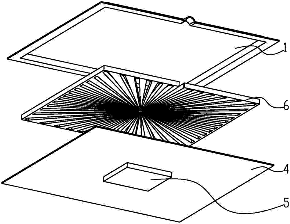
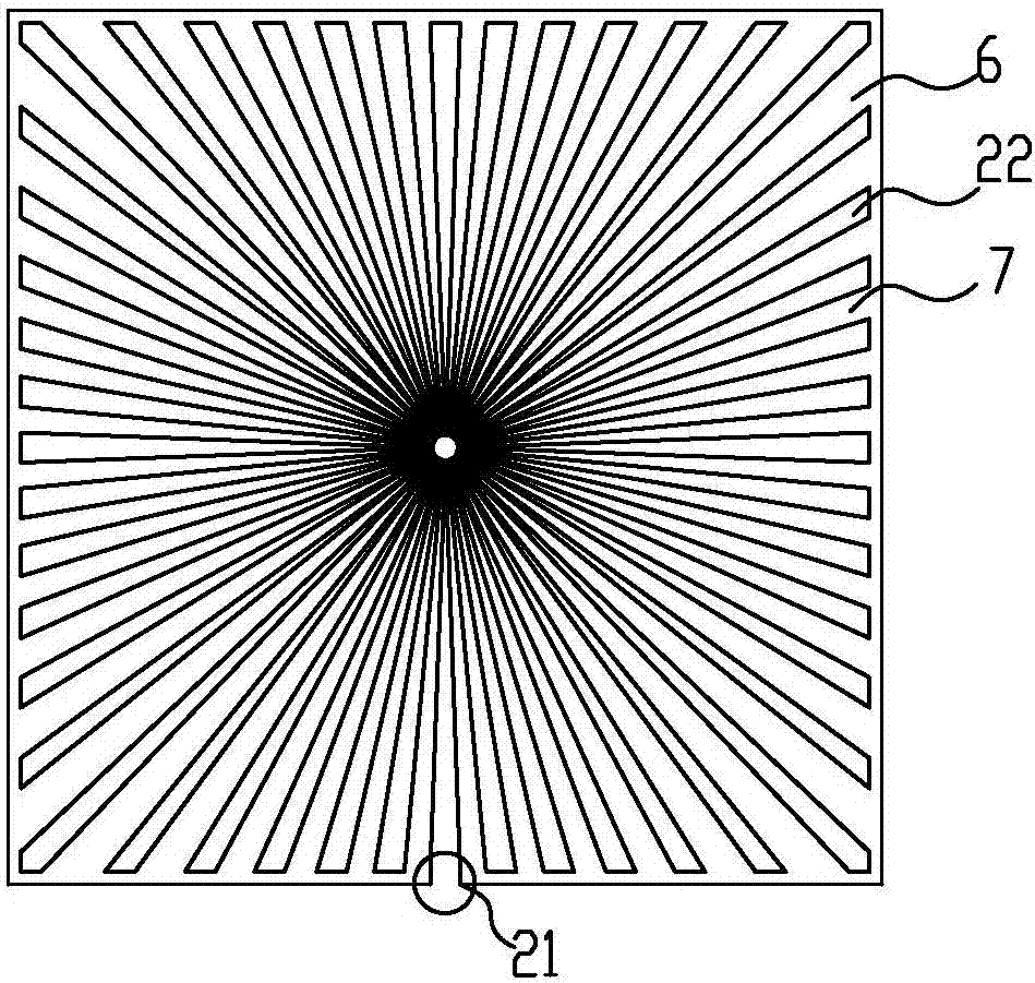
[0035] Such as figure 1 , image 3 , Figure 5 , Figure 6 As shown, an ultra-thin vapor chamber includes: an upper shell 1, a layer of liquid-absorbing core 2 and a lower shell 4 arranged in sequence, the lower surface of the upper shell 1 and the uppermost liquid-absorbing core 2 The upper surface is affixed, the bottom surface of the bottom liquid-absorbing core 2 is affixed to the upper surface of the lower shell 4, and the center of the heat source 5 located in the lower shell 4 or the upper shell 1 is centered on the liquid-absorbing core 2. The annular array is provided with several channels 22 that gradually widen outwards from the center, and between adjacent channels 22 are liquid-absorbing core strips 7, and this layer of liquid-absorbing core 2 is called channel liquid-absorbing core 6, and the grooves The ratio between the depth of the channel 22 and the total thickness of all the liquid-absorbing cores 2 is greater than 1:2, and the angle between the centerlin...

Embodiment 2

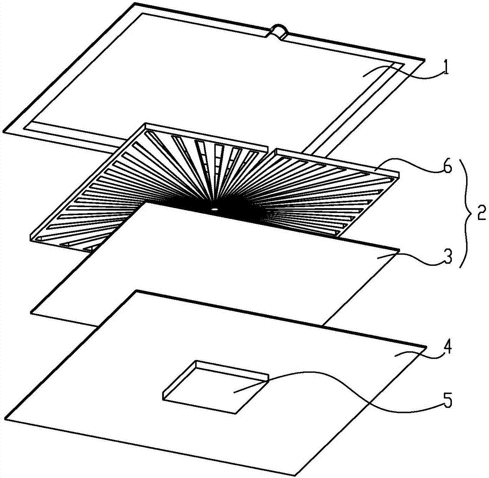
[0041] The main structure of this embodiment is the same as that of Embodiment 1, and the similarities will not be repeated here. The difference from Embodiment 1 is that: figure 2 , Figure 7 , Figure 8 As shown, the liquid-absorbent core 2 is arranged in two layers including the channel liquid-absorbent core 6 provided with the channel 22 and the conventional liquid-absorbent core 3 , and the channel liquid-absorbent core 6 provided with the channel 22 is arranged away from the heat source 5 .

[0042] The heat source 5 is placed at the center of the bottom of the lower shell plate 4 of the vapor chamber, which is also the center of the divergence of the liquid absorbing core 6 of the channel. The lower surface of the conventional liquid-absorbing core 3 is affixed to the upper surface, and the lower surface of the conventional liquid-absorbing core 3 is affixed to the upper surface of the lower shell plate 4. In this way, the channel 22 of the channel liquid-absorbing c...

Embodiment 3

[0044] The main structure of this embodiment is the same as that of Embodiment 1, and the similarities will not be repeated here. The difference from Embodiment 1 is that: Figure 4 As shown, with the center as the center of the circle, the ratio of the total width of the channel 22 on the same circumference to the width of the total liquid-absorbent core strip 7 is less than or equal to 2:1, with the center as the center of the circle, the ratio of the total width of the channel 22 on the same circumference is less than or equal to 2:1. Where the ratio of the width to the width of the adjacent liquid-absorbing core side strip 7 is less than or equal to 1:3, a branch channel 23 is provided, and the maximum width of the channel 22 is ≤3mm. When the area of ​​the vapor chamber is large, since the thickness of the upper and lower shell plates 4 is only 0.03-0.3mm, in order to ensure sufficient support strength, the maximum distance between the channels 22 shall not exceed 3mm, whi...


PUM


Abstract

The invention relates to an ultrathin heat homogenizing plate structure. The ultrathin heat homogenizing plate structure comprises an upper shell plate, at least one layer of liquid suction core and a lower shell plate which are sequentially arranged. The lower surface of the upper shell plate is fixedly connected with the upper surface of the uppermost layer of the liquid suction core, and the bottom face of the bottommost layer of the liquid suction core is fixedly connected with the upper surface of the lower shell plate. By using the center of a heat source located on the lower shell plate or the upper shell plate as a center, a plurality of channels which are diffused outwards from the centers and are gradually widened are formed in one layer of the liquid suction core in a ring array mode. The effect of arranging the channels which are diffused outwards and are gradually widened by using the center of the heat source as the center is to provide diffusion paths of working medium steam. A working medium is diffused in all directions along the channels after being evaporated, the purpose of arranging the center of the heat source to be the diffused channel center lies in that the evaporated working medium carries heat of the heat source to be diffused to a whole heat homogenizing plate, the condensed working medium can flow back to the heat source position to be recycled continuously under the capillary force action of the liquid suction cores, and the ultrathin heat homogenizing plate can effectively solve the heat radiating problem of high heating flux electronic components in a narrow space through the principle of phase change heat transfer.

Description

technical field [0001] The invention relates to the technical field of heat transfer devices, in particular to an ultra-thin vapor chamber structure. Background technique [0002] With the improvement of the integration of electronic products, the packaging space of electronic chips is getting smaller and smaller, which leads to the reduction of chip heat dissipation area and the increase of heat flux density in the field of microelectronics. The reliability of electronic components drops sharply with the rise of temperature, and the hot spots generated by high heat flux seriously affect their performance and life. Traditional aluminum and copper heat sinks with fins can no longer meet the heat dissipation requirements of high heat flux devices. [0003] Existing vapor chambers are usually arranged regularly between the upper and lower shell plates for support, and the steam channel is located above the liquid-absorbing core. Chinese patent CN102706193 B discloses a radial...

Claims


Application Information

Patent Timeline
Patent Type & Authority Applications(China)
IPC IPC(8): F28D15/04
CPCF28D15/046
Inventor 黄光文李勇周文杰何柏林陈韩荫陈创新
Owner SOUTH CHINA UNIV OF TECH
Why Eureka
Try Eureka