
Optical receiving module, packaging structure and packaging method thereof

A light-receiving module and packaging structure technology, applied in the directions of light guides, optics, optical components, etc., can solve the problems of small displacement deviation, unfavorable mass production, complicated processes, etc., to reduce the number of coupling alignments, and facilitate mass production. Mass production, beneficial effects on quality and cost control

Inactive Publication Date: 2017-11-28
LINKTEL TECH CO LTD
View PDF6 Cites 10 Cited by
  • Summary
  • Abstract
  • Description
  • Claims
  • Application Information

AI Technical Summary

Problems solved by technology

[0006] The purpose of the present invention is to overcome the defects of the prior art and provide a packaging structure for light receiving modules, which solves the problem that there are many optical components in the packaging process, the positioning accuracy of the components is high, and the displacement deviation after fixing is required to be small, resulting in complicated procedures and unnecessary Problems conducive to mass production

Method used


Image

  • Optical receiving module, packaging structure and packaging method thereof
  • Optical receiving module, packaging structure and packaging method thereof
  • Optical receiving module, packaging structure and packaging method thereof

Examples


Embodiment Construction

[0030] The following will clearly and completely describe the technical solutions in the embodiments of the present invention with reference to the accompanying drawings in the embodiments of the present invention. Obviously, the described embodiments are only some, not all, embodiments of the present invention. Based on the embodiments of the present invention, all other embodiments obtained by persons of ordinary skill in the art without making creative efforts belong to the protection scope of the present invention.

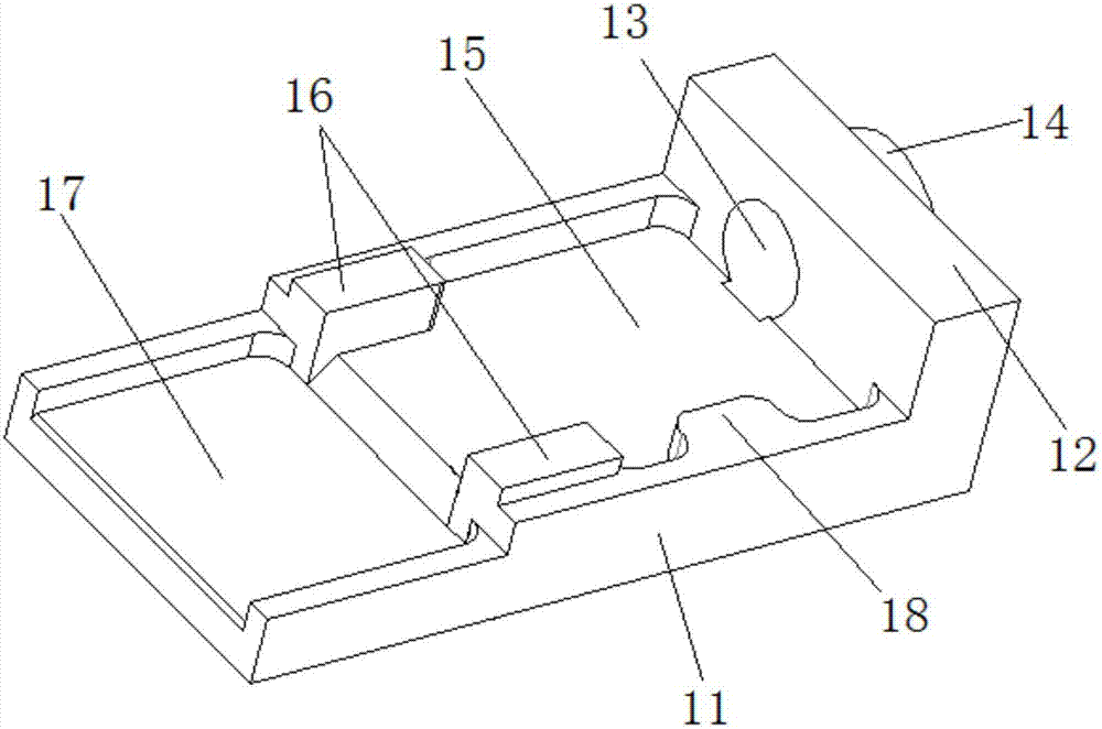
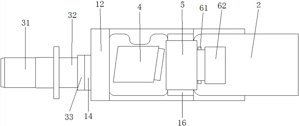
[0031] Such as Figure 1-Figure 4 , the embodiment of the present invention provides a package structure of a light receiving module, which includes a tube case 1, the tube case includes a flat plate 11, one end of the flat plate 11 is vertically connected to a connecting plate 12, and a circle is opened on the connecting plate 12. Shaped adapter positioning hole 13, the adapter positioning hole 13 is matched with the size of the adapter for positioning the ad...


PUM


Abstract

The invention relates to the field of optical packaging, and provides a packaging structure of an optical receiving module. The packaging structure comprises a tube shell. The tube shell comprises a flat board. One end of the flat board is vertically connected with a connecting board. The connecting board is provided with a circular adapter locating hole. One surface, which is far from the flat board, of the connecting board is provided with an annular welding boss around the adapter locating hole. The flat board is provided with an optical demultiplexing locating recessed trough, supporting bosses and a flexible circuit board locating recessed trough, wherein the optical demultiplexing locating recessed trough, the supporting bosses and the flexible circuit board locating recessed trough are successively arranged in a direction of separating from the connecting board. The sidewall of the optical demultiplexing locating recessed trough is provided with a projected alignment boss. Two supporting bosses are arranged. The packaging structure of the optical receiving module is a multi-component assembly which is machined through a precise machinery. According to the packaging structure and the packaging method, corresponding optical packaging can be finished through one-time multichannel light beam quality analysis and one-time active optical coupling alignment process, thereby greatly simplifying an optical coupling alignment process.

Description

technical field [0001] The invention relates to the field of optical packaging, in particular to a packaging structure and a packaging method of a light receiving module. Background technique [0002] Along with the process of digitization, data processing, storage and transmission have been developed rapidly. The rapid growth of search services with large amounts of data and video services has greatly promoted the development of data centers based on supercomputers and storage. 40G / 100G QSFP+ optical module, as the main product for short-distance data center interconnection applications, has broad market application prospects. The design idea of ​​the data center optical module is to provide higher access density through smaller volume and lower cost, and ultimately increase user access capacity. [0003] Due to the fact that the parallel transceiver optical module can provide greater transmission bandwidth under the premise of smaller space and lower energy consumption, ...

Claims


Application Information

Patent Timeline
IPC IPC(8): G02B6/42
CPCG02B6/4237G02B6/4243G02B6/4246G02B6/4255G02B6/4281G02B6/4287
Inventor 胡定坤张健杨现文吴天书李林科
Owner LINKTEL TECH CO LTD
Learn More