Uplink data transmission method and system, user device and base station

A data transmission method and base station technology, applied in user equipment and base stations, uplink data transmission method and system field, can solve problems such as inability to meet deep coverage, packet loss, frequent retransmission, etc.

Inactive Publication Date: 2017-11-28
CHINA MOBILE COMM LTD RES INST +1
View PDF5 Cites 6 Cited by
  • Summary
  • Abstract
  • Description
  • Claims
  • Application Information

AI Technical Summary

Problems solved by technology

Since the size of a SIP message is hundreds of times the size of a Radio Resource Control (RRC, Radio Resource Control) message, although it has been properly optimized on the wireless side, it still cannot meet the requirements of deep coverage after optimization.
Especially when the UE is in a weak coverage area, and the UE requests resources from the evolved base station (eNB, evolved Node B) according to the actual size of the SIP message, in this case, the data packets that the UE needs to transmit in the uplink will exceed its own transmission capacity, thus It will cause packet loss and frequent retransmission, which will affect the performance of VoLTE calls

Method used


Image

  • Uplink data transmission method and system, user device and base station
  • Uplink data transmission method and system, user device and base station
  • Uplink data transmission method and system, user device and base station

Examples


Embodiment 1

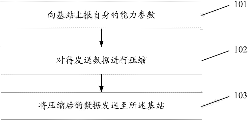
[0107] This embodiment provides a method for uplink data transmission, which is applied to UE, such as figure 1 As shown, the method includes the following steps:

[0108] Step 101: The UE reports its own capability parameters to the base station;

[0109] Here, the reported capability parameter can indicate that the UE has a data compression capability.

[0110] In practical applications, the timing for performing step 101 may be: when the UE initially attaches, when the UE performs random access, or when the UE periodically reports its own capability parameters.

[0111] In actual application, the specific implementation of this step may include:

[0112] The UE adds a first variable (new variable, which may be named DataCompressionIndex) to the UE Capability parameter, that is, the UE Capability parameter includes the first variable, and the first variable indicates the The UE supports data compression capability; and sends the UE Capability parameter to the base station...

Embodiment 2

[0194] On the basis of the first embodiment, this embodiment uses the UE to report a specific compression algorithm to illustrate the uplink data transmission process.

[0195] The UE reports the compression algorithm A supported by itself to the eNB, and decides to compress the data packet at the application layer.

[0196] The UE uses the compression algorithm A to compress the data packets of the application layer, and sends them to the eNB after compression.

[0197] After eNB receives the data packet of the application layer sent by the UE, it determines that the UE supports the data compression function according to the compression algorithm reported by the UE, so it decompresses the data packet of the UE application layer according to the preset compression algorithm A, and then forwards it to the core network.

Embodiment 3

[0199] On the basis of the first embodiment, this embodiment describes the uplink data transmission process by using the set of compression algorithms reported by the UE.

[0200] The UE reports the compression algorithm set Ω supported by itself to the eNB, which includes three compression algorithms A, B, and C, and decides to compress the data packet at the network layer.

[0201] The UE uses any compression algorithm (compression algorithm A, B, or C) in the compression algorithm set Ω to compress the data packets at the network layer, and sends the compressed data packets to the eNB.

[0202] After receiving the network layer data packet sent by the UE, the eNB determines that the UE supports the data compression function according to the compression algorithm reported by the UE, so according to the preset compression algorithm set, the UE network layer data packet is decompressed by blind detection , and then forwarded to the core network.


PUM


Abstract

The invention discloses an uplink data transmission method. The uplink data transmission method comprises that: user equipment (UE) reports parameters of self-capabilities to a base station; the reported parameters of the self-capabilities can indicate that the UE has a data compressing capability; on the basis of the data compressing capability, compression is performed on data to be transmitted; and the compressed data is transmitted to the base station. The invention also discloses an UE, a base station and an uplink data transmission system.

Description

technical field [0001] The present invention relates to the field of wireless communication, in particular to an uplink data transmission method and system, user equipment (UE, User Equipment) and a base station. Background technique [0002] The Voice (VoLTE) service carried on the Long Term Evolution network is a voice service based on an IP Multimedia Subsystem (IMS, IP Multimedia Subsystem). For the VoLTE service, in an area with weak wireless signal quality, a Session Initiation Protocol (SIP, Session Initiation Protocol) message may fail to be sent or lost when a call is initiated. Since the size of a SIP message is hundreds of times the size of a Radio Resource Control (RRC, Radio Resource Control) message, although it has been properly optimized on the wireless side, it still cannot meet the requirements of deep coverage after optimization. Especially when the UE is in a weak coverage area, and the UE requests resources from the evolved base station (eNB, evolved No...

Claims


Application Information

Patent Timeline
IPC IPC(8): H04W28/06H04W28/18
CPCH04W28/06H04W28/18H04W8/22H04W28/065
Inventor 陈俊刘磊
Owner CHINA MOBILE COMM LTD RES INST
Why Eureka
Try Eureka