Plate overturning machine and plate overturning method

A panel turning machine and panel technology, which is applied in the direction of conveyors, conveyor objects, transportation and packaging, etc., to achieve the effect of not being easy to shift, high stability, and maintaining the quality of the panel

Pending Publication Date: 2017-12-01
QUANYOU FURNITURE
View PDF12 Cites 12 Cited by
  • Summary
  • Abstract
  • Description
  • Claims
  • Application Information

AI Technical Summary

Problems solved by technology

[0005] The purpose of the present invention is to provide a plate turning machine and a turning method, which are used to improve the defect that the existing processing equipment needs manual turning

Method used


Image

  • Plate overturning machine and plate overturning method
  • Plate overturning machine and plate overturning method
  • Plate overturning machine and plate overturning method

Examples


Embodiment 1

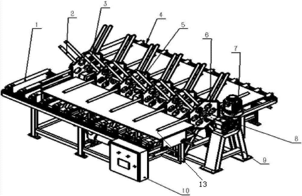
[0036] In order to facilitate the installation of parallel forks, in this embodiment, preferably, the left view of the mounting plate 5 is a regular hexagonal structure, and the parallel forks 2 are respectively installed in the middle of the six end faces of the mounting plate 5 of 6 groups. By setting a mounting plate in the shape of a regular hexagon, when installing the parallel fork, the two rod bodies constituting the parallel fork can be conveniently fixed on the mounting plate, and the parallel fork can be positioned conveniently, so that the two rod bodies constituting the parallel fork The length is easier to control. During installation, parallel forks are respectively set on the 6 end faces of the mounting plate, so that they can be used to clamp the plate.

[0037] When the rotating shaft rotates, through the parallel forks arranged on the six end surfaces, the parallel forks on the two opposite end surfaces are respectively parallel to the feeding conveyor and th...

Embodiment 2

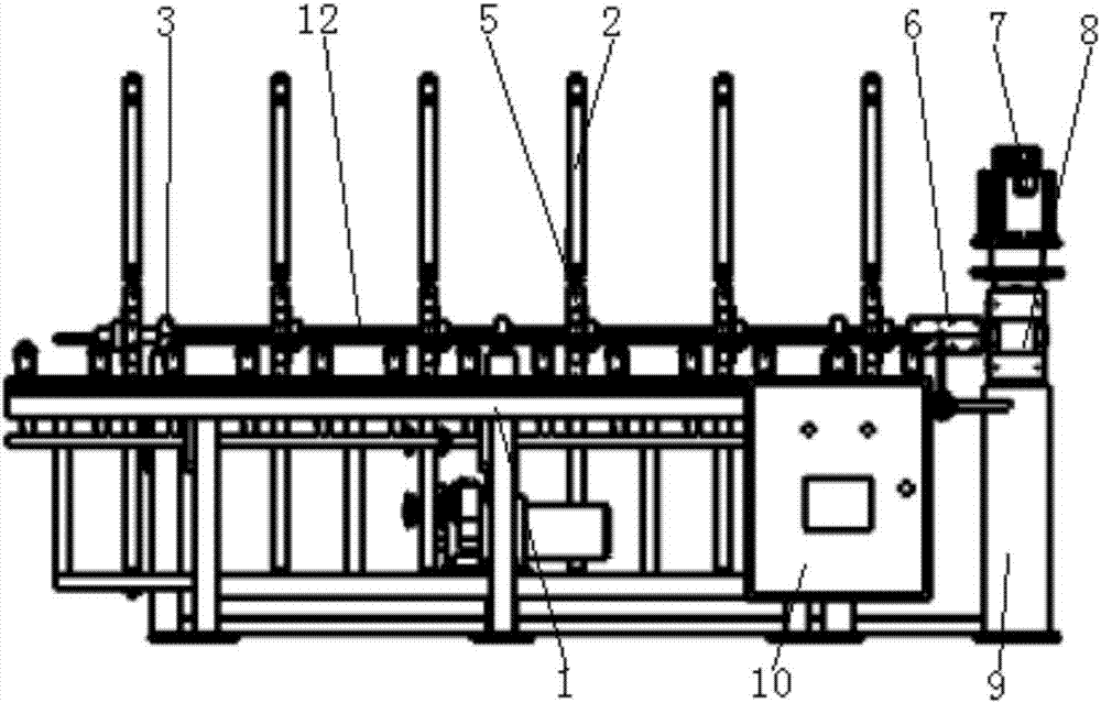
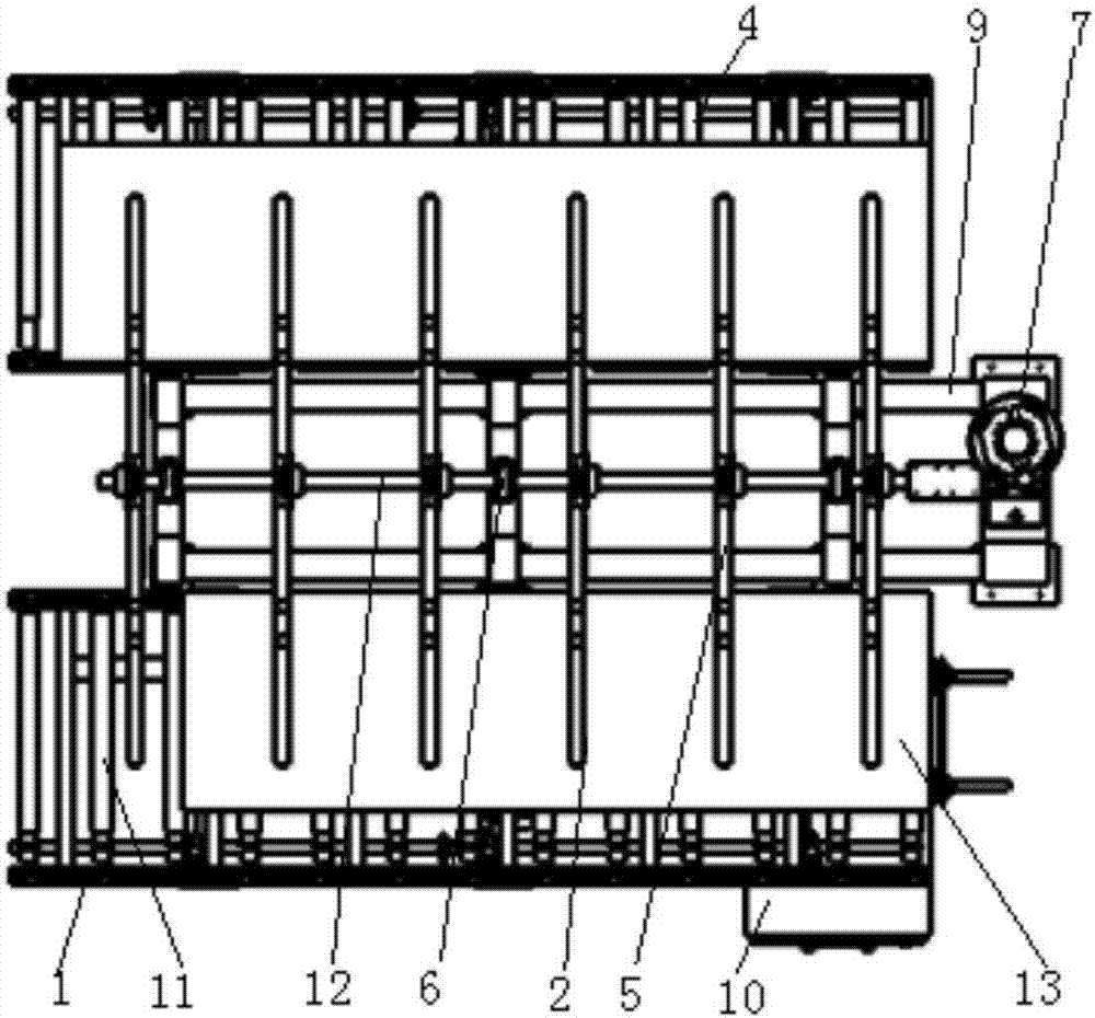
[0041] In order to improve the stability of the rotating shaft, in this embodiment, preferably, uniformly distributed brackets are arranged on the frame 9 , and the rotating shaft 12 is rotatably connected to the upper end of the bracket through the bearing seat 3 . By setting the bracket, the rotating shaft is rotatably connected to the bearing seat at the upper end of the bracket, and when the rotating shaft rotates relatively, the bracket supports the rotating shaft from the end far away from the coupling, thereby avoiding the rotating shaft from tilting when the force on both ends of the rotating shaft is uneven.

[0042] When transporting the sheet, once the force exerted by the sheet on the rotating shaft is unbalanced, causing unequal forces on both ends of the rotating shaft, the bracket structure in this embodiment can provide support for the rotating shaft from below to keep the sheet in a stable state.

[0043] In order to facilitate the centralized control of the op...

Embodiment 3

[0045] At the same time, the invention also discloses a board turnover method, which includes the following steps:

[0046] S1: Fix the parallel fork: start the servo motor 7, and drive the rotating shaft 12 to rotate through the matching reducer 8, so that the mounting plate 5 on the rotating shaft 12 drives the parallel fork 2 to rotate, so that the two rods constituting the parallel fork 2 All parallel to the conveying roller 1 of the feed conveyor 1, so that the upper end surface of the cavity 15 formed between the two rods is higher than the upper end surface of the conveying roller 1, and the servo motor 7 is stopped to keep the parallel fork 2 stable , stop the servo motor 7;

[0047] S2: Input plate: place the plate on the conveying roller 1 of the feeding conveyor 1, and when the driving device drives the conveying roller 1 to rotate, when the plate 13 moves along the feeding conveyor 1, the plate 13 is plugged into the step Inside the cavity 15 formed in S1;

[004...


PUM


Abstract

The invention discloses a plate overturning machine. The plate overturning machine comprises a frame, and a feed conveyor and a discharge conveyor symmetrically arranged on two sides of the frame; conveying rollers are uniformly distributed on the feed conveyor and the discharge conveyor; driving devices for driving the conveying rollers to rotate are respectively arranged below the feed conveyor and the discharge conveyor; the frame is provided with a servo motor and a matched speed reducer; a rotating shaft is arranged above the frame; the speed reducer drives the rotating shaft to rotate through a coupling; at least two mounting plates are arranged on the rotating shaft; parallel forks for clamping plates are arranged on the mounting plates; and when the mounting plates are rotated along with the rotating shaft, the parallel forks can clamp the plates to overturn from the feed conveyor onto the discharge conveyor. The plate overturning machine can be used for improving the defect of manual overturning of the plates in traditional processing equipment.

Description

technical field [0001] The invention relates to the field of furniture processing, in particular to a plate turning machine and a turning method. Background technique [0002] In the process of furniture processing, both end faces of the board need to be processed when processing the board. The traditional operation is to process the other side after one side of the workpiece is processed. The workpiece is turned over manually, and the labor intensity of the workers is high. . [0003] In the invention patent with the authorized notification number CN203382190U, a plate turning machine is disclosed. The turning machine includes a base, a rotating shaft and two brackets. The two brackets are symmetrically fixed on the base, and each bracket is equipped with a bearing seat. The two ends of the rotating shaft are respectively fixed on the bearing seats of the two brackets through bearings. One end of the rotating shaft is the power input end, which drives the rotating shaft to...

Claims


Application Information

Patent Timeline
Patent Type & Authority Applications(China)
IPC IPC(8): B65G47/248B65G47/52
CPCB65G47/248B65G47/52B65G2201/022
Inventor 张鸾军叶壮
Owner QUANYOU FURNITURE
Why Eureka
Try Eureka