
Automatic material distribution device and method for stock bins

An automatic material distribution and silo technology, applied in conveyor control devices, packaging, loading/unloading, etc., can solve problems such as unhealthy physical and mental health of workers, unreasonable material distribution in silos, and inability to implement on-site operations in workshops and scheduling rooms. , to achieve the effect of reducing mechanical and electrical accidents and cost input, reducing the possibility of occupational diseases, and avoiding empty warehouses or ore pressing accidents

Inactive Publication Date: 2017-12-01
ANSTEEL GRP MINING CO LTD
View PDF9 Cites 13 Cited by
  • Summary
  • Abstract
  • Description
  • Claims
  • Application Information

AI Technical Summary

Problems solved by technology

[0002] The silo is the buffer and storage device in the mine production, and it is an important part of the mine production. The existing material distribution is based on the observation of the material level of the silo by the operator, and then the manual control of the material. Due to the large dust on site, the work intensity Large, causing great harm to operators, in addition, there are the following disadvantages:
[0003] 1. Manually control the unloading trolley, resulting in unreasonable material distribution in the silo, and prone to silo emptying or mine crushing accidents;
[0004] 2. When the operator observes the material level of the silo, it is easy to be wounded by the belt conveyor, injured by the unloading trolley, derailed by the unloading trolley and other safety accidents;
[0005] 3. During continuous production, workers need to frequently operate the mobile unloading trolley to control the balance of the material level in the mine bin, which is labor-intensive;
[0006] 4. The on-site environment is harsh, with serious dust and noise pollution, which is extremely detrimental to the physical and mental health of workers;
[0007] 5. Automatic material distribution cannot be realized, and the workshop and dispatch room cannot implement and grasp the on-site operation situation

Method used


Image

  • Automatic material distribution device and method for stock bins
  • Automatic material distribution device and method for stock bins
  • Automatic material distribution device and method for stock bins

Examples


Embodiment Construction

[0038] The specific implementation manner of the present invention will be further described below in conjunction with the accompanying drawings.

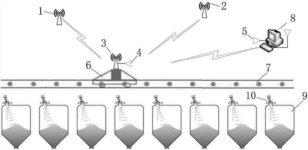
[0039] Such as figure 1 , 2 , 3, 4 and 5, the automatic material distribution device for the silo of the present invention includes a silo 9, a belt conveyor 7 arranged above the silo 9, and a belt conveyor 7 arranged on the belt conveyor 7 for unloading The trolley 6 is characterized in that it also includes a positioning device for the unloading trolley of the belt conveyor, a material level detection device for the silo,

[0040] The belt conveyor unloading trolley positioning device includes an anchor node A1, an anchor node B2, a label node 3, a wireless data transmission RF433 module II5 connected to the label node 3, and a wireless data transmission RF433 module II5 connected to the wireless data transmission RF433 module II5. The control system 8, the anchor node A1 and the anchor node B2 respectively complete the distanc...


PUM


Abstract

The invention belongs to the technical field of material distribution methods and particularly relates to an automatic material distribution device and method for stock bins. The automatic material distribution device for the stock bins comprises the stock bins, a belt conveyor arranged above the stock bins and a belt conveyor discharging trolley arranged on the belt conveyor. The automatic material distribution bin is characterized by further comprising a belt conveyor discharging trolley positioning device and a stock bin material position detection device. According to the automatic material distribution device and method for the stock bins, the full-automatic uniform material distribution can be achieved, the empty bin or the ore pressing accident is avoided, the unattended purpose can be achieved, the workers are downsized, the possibility of occupational diseases is lowered greatly, the health of the operation workers is guaranteed, and the purposes of downsizing the staff and improving the efficiency are achieved; and in addition, by the adoption of the automatic material distribution device and method for the stock bins, the economic benefits are increased, and the reliable reference can be provided for the daily overhauling work, so that the mechanical and electrical accidents are reduced, and the cost input is reduced.

Description

technical field [0001] The invention belongs to the technical field of material distribution methods, and in particular relates to an automatic material distribution device and a material distribution method for a silo. Background technique [0002] The silo is the buffer and storage device in the mine production, and it is an important part of the mine production. The existing material distribution is based on the observation of the material level of the silo by the operator, and then the manual control of the material. Due to the large dust on site, the work intensity Large, causing great harm to operators, in addition, there are the following disadvantages: [0003] 1. Manually control the unloading trolley, resulting in unreasonable material distribution in the silo, and prone to silo emptying or mine crushing accidents; [0004] 2. When the operator observes the material level of the silo, it is easy to be wounded by the belt conveyor, injured by the unloading trolley,...

Claims


Application Information

Patent Timeline
IPC IPC(8): B65G65/32B65G43/00B65G47/34B65D90/48
CPCB65G65/32B65D90/48B65G43/00B65G47/34
Inventor 马连成肖成勇齐向东何杰
Owner ANSTEEL GRP MINING CO LTD
Learn More