Evaporator

A technology for evaporators and evaporator tubes, applied in chemical instruments and methods, heating water/sewage treatment, water/sewage treatment, etc., can solve the problems of heat transfer performance decline, heat transfer efficiency drop of evaporator heat exchange tubes, easy to block, etc. problem, to achieve the effect of accelerating evaporation time, prolonging operation cycle and increasing heat exchange efficiency

Pending Publication Date: 2017-12-01
ANHUI PROVINCE CHEM IND DESIGN INST
View PDF6 Cites 1 Cited by
  • Summary
  • Abstract
  • Description
  • Claims
  • Application Information

AI Technical Summary

Problems solved by technology

[0002] In the prior art, the evaporator in the sewage treatment plant generally adopts a common conventional evaporator structure, because some materials in the production equipment in the project have many impurities, high viscosity, and are easy to block; moreover, after a period of use, the evaporator needs to be replaced Significant drop in thermal performance
Generally, the evaporator has the fo

Method used


Image

  • Evaporator
  • Evaporator
  • Evaporator

Examples


Example Embodiment

[0018] The embodiments of the present invention will be described in detail below with reference to the accompanying drawings, but the present invention can be implemented in many different ways defined and covered by the claims.

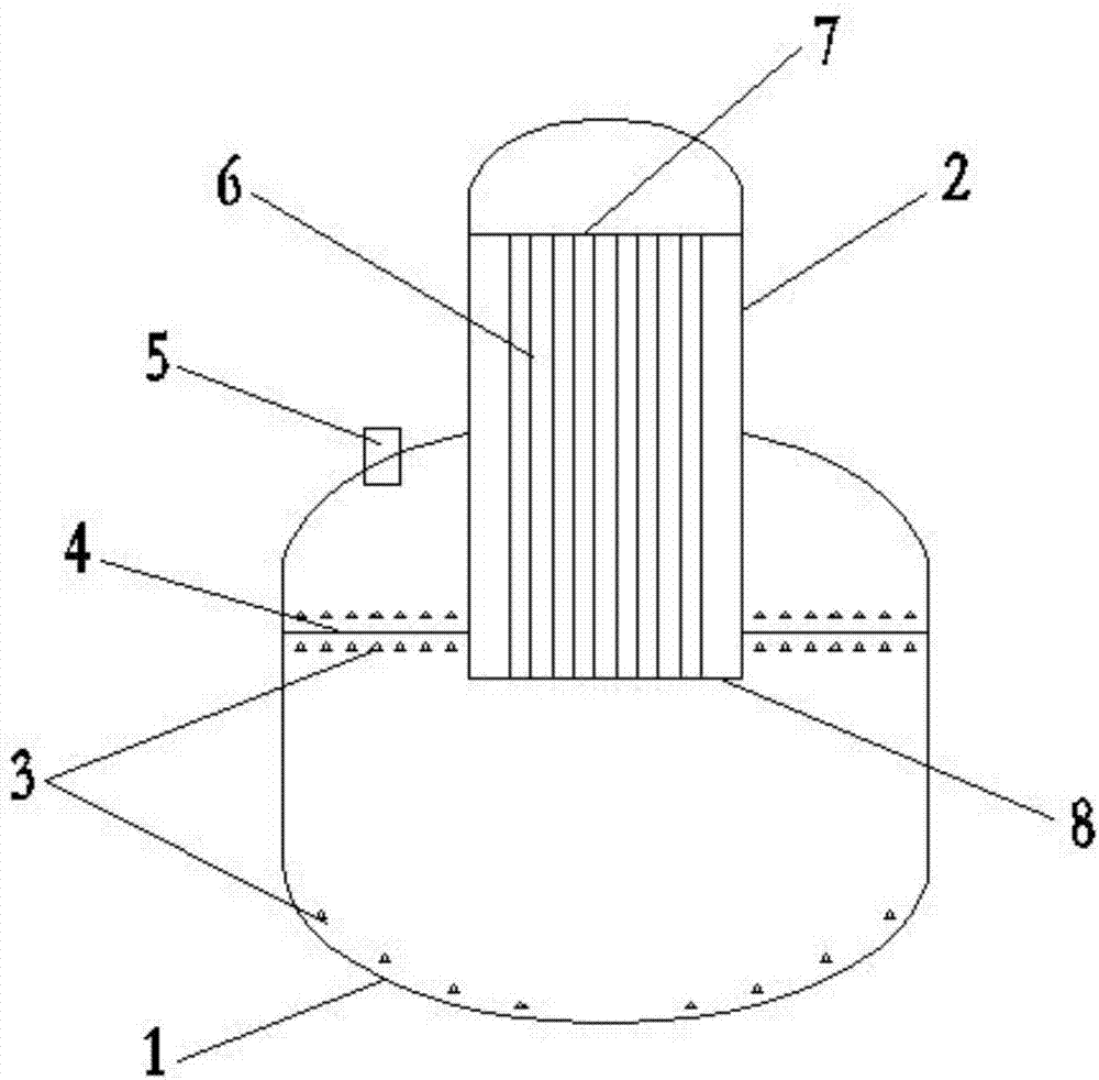
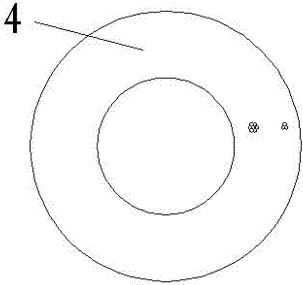
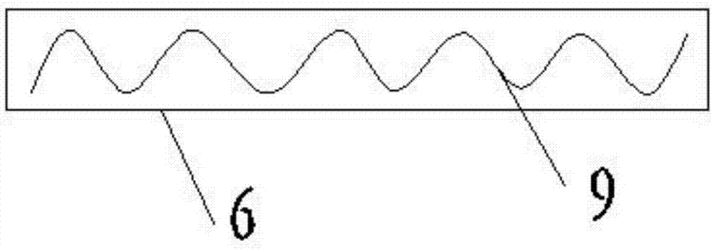
[0019] Such as figure 1 As shown, the present invention discloses an evaporator, including a box body 1 and an evaporation tube 2 inserted vertically from the upper part of the box body 1; an aeration device 3 is provided at the bottom of the box body 1, and the aeration device 3 is located inside the box body 1. The inside of the box body 1 is provided with a filter plate 4, the filter plate 4 divides the inside of the box body 1 into upper and lower parts, the lower end of the evaporation tube 2 passes through the filter plate 4, and the connection with the filter plate 4 is sealed The upper end of the box body 1 has a head structure 5 with holes, such a head structure 5 and the box body 1 and the filter plate 4 form a closed small space, and the evap...


PUM


Abstract

The invention discloses an evaporator which comprises a box and an evaporating pipe directly inserted in the box from the upper portion of the same. Aerating apparatus are arranged at the bottom of the box and are located in the box, a filter plate is arranged in the box, and the lowermost end of the evaporating pipe penetrates the filter plate; a heat exchange pipe is arranged in the evaporating pipe, an upper pipe retaining plate and a lower pipe retaining plate are respectively arranged at upper and lower ends of the heat exchange pipe, and the lower pipe retaining plate is located at the lower end of the filter plate; an end socket structure provided with a hole is arranged at the upper end of the box. By the arrangement, heat efficiency of the heat exchange pipe of the evaporator is stable or is decreased in an unobvious manner within a long period; fluid in the heat exchange pipe is mainly turbulent, and heat exchange efficiency is increased; utilization of low-grade steam in the production device is increased; the evaporator is effective as well when material separation temperature is small in different; after two-effect or multi-effect serial connection, utilization rate of the steam is increased; the evaporator is long in running cycle, low in labor cost, high in evaporation efficiency and fast in evaporation time.

Description

technical field [0001] The invention relates to the field of evaporators, in particular to evaporators in sewage treatment devices in pharmaceutical projects, pesticide projects and fine chemical projects. Background technique [0002] In the prior art, the evaporator in the sewage treatment plant generally adopts a common conventional evaporator structure, because some materials in the production equipment in the project have many impurities, high viscosity, and are easy to block; moreover, after a period of use, the evaporator needs to be replaced The thermal performance drops significantly. General evaporators have the following disadvantages: 1. The heat exchange efficiency of the evaporator heat exchange tubes decreases significantly with time. 2. The fluid in the heat exchange tube is mostly laminar flow. 3. The residence path of the evaporation section is short. 4. When the material separation temperature difference in the evaporator is small, the effect is not obv...

Claims


Application Information

Patent Timeline
IPC IPC(8): C02F1/00C02F1/04
CPCC02F1/001C02F1/04C02F1/043
Inventor 雷明华徐慧刘梅李光明范鑫
Owner ANHUI PROVINCE CHEM IND DESIGN INST
Why Eureka
Try Eureka