Aeroengine combustor rotational sliding arc plasma combustion-supporting actuator

A technology of aero-engine and plasma, which is applied in the direction of plasma, machine/engine, mechanical equipment, etc. It can solve the problems of complex structure, inability to adapt to the harsh working environment of the aero-engine combustion chamber, and large size, so as to improve combustion efficiency, Simplified geometry and dynamics, small size effects

Inactive Publication Date: 2017-12-01
AIR FORCE UNIV PLA
View PDF7 Cites 23 Cited by
  • Summary
  • Abstract
  • Description
  • Claims
  • Application Information

AI Technical Summary

Problems solved by technology

[0006] In order to overcome the disadvantages of complex structure and large size in the prior art, which cannot adapt to the harsh working environment of the aero-engine combustor, the present invention proposes a rotary sliding arc plasma combustion-supporting actuator for the aero-engine combustor

Method used


Image

  • Aeroengine combustor rotational sliding arc plasma combustion-supporting actuator
  • Aeroengine combustor rotational sliding arc plasma combustion-supporting actuator
  • Aeroengine combustor rotational sliding arc plasma combustion-supporting actuator

Examples


Embodiment 1

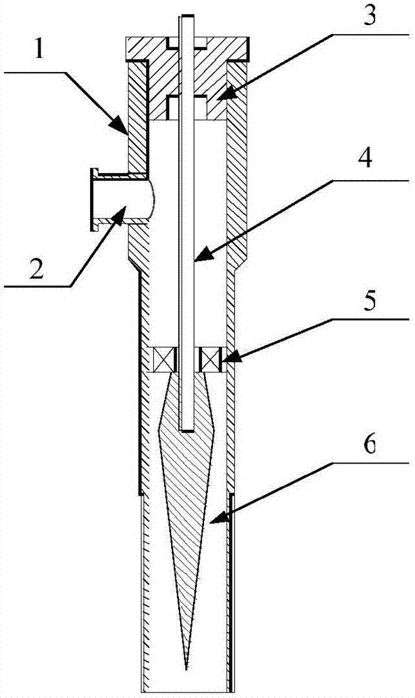
[0035] This embodiment is a rotary sliding arc plasma combustion-supporting exciter for an aero-engine combustor, including an anode casing 1, an air intake nozzle 2, an electrode installation isolation seat 3, a cathode electrode rod 4, a swirler 5 and a cathode cone electrode 6. Wherein, the cyclone 5 is located in the middle section of the inner hole of the anode casing 1 . The cathode cone electrode 6 is located below the round-hole axial flow cyclone; the lower end of the cathode electrode rod 4 passes through the central hole of the round-hole axial flow cyclone 5 and is inserted into the cathode cone In the central blind hole on the upper end face of the body electrode; the upper end of the cathode electrode rod is put into the center hole of the electrode installation isolation seat 3, and the upper end of the cathode electrode rod extends out of the upper surface of the electrode installation isolation seat. The electrode installation isolation seat 3 is fixedly inst...

Embodiment 2

[0044] This embodiment is a rotary sliding arc plasma combustion-supporting exciter for an aero-engine combustor, including an anode casing 1, an air intake nozzle 2, an electrode installation isolation seat 3, a cathode electrode rod 4, a swirler 5 and a cathode cone electrode 6.

[0045] This embodiment is a rotary sliding arc plasma combustion-supporting exciter for an aero-engine combustor, including an anode casing 1, an air intake nozzle 2, an electrode installation isolation seat 3, a cathode electrode rod 4, a swirler 5 and a cathode cone electrode 6. Wherein, the cyclone 5 is located in the middle section of the inner hole of the anode casing 1 . The cathode cone electrode 6 is located below the vane-type axial flow swirler; the lower end of the cathode electrode rod 4 passes through the central hole of the swirler 5 and is inserted into the center of the upper end surface of the cathode cone electrode. In the blind hole; the upper end of the cathode electrode rod i...


PUM


Abstract

The invention discloses an aeroengine combustor rotational sliding arc plasma combustion-supporting actuator. An axial flow cyclone is arranged at the middle section in an anode shell; a cathode cone electrode is arranged below a round hole type axial flow cyclone; the lower end of a cathode electrode rod penetrates through a center hole of the round hole type axial flow cyclone and is charged into a center blind hole formed in the upper end surface of the cathode cone electrode; the upper end of the cathode electrode rod is charged into a center hole formed in an electrode mounting isolation seat; the electrode mounting isolation seat is fixed at the end of a large diameter section of an inner hole of the anode shell; and an air inlet nozzle which is connected with an engine gas supply device in a sealing manner is installed on the outer circumferential surface of the large diameter section of the anode shell. The aeroengine combustor rotational sliding arc plasma combustion-supporting actuator is capable of improving the combustion efficiency of an aeroengine combustor and the uniformity of an outlet of the combustor and expanding the stable combustion range of the combustor, overcomes the deficiency that the existing plasma combustion-supporting technology is not suitable for being used in a high-temperature and high-pressure environment of the aeroengine combustor and has the characteristics of capability of producing a great amount of active particles, small size, simple structure, strong universality and the like.

Description

technical field [0001] The invention relates to plasma combustion enhancement technology in the field of aerodynamics, in particular to a rotary sliding arc plasma combustion-supporting exciter for an aeroengine combustion chamber. Background technique [0002] As the performance of fighter jets continues to improve, higher requirements are placed on the performance of aero-engines. The U.S. Department of Defense has proposed the "Comprehensive High-Performance Turbine Engine Technology Plan", with the goal of doubling the thrust-to-weight ratio of aero-engines by the beginning of the 21st century. , that is to reach 15-20. One of the most effective ways to increase the thrust-to-weight ratio is to increase the unit thrust of the engine, and an effective way to increase the unit thrust is to increase the temperature at the outlet of the combustion chamber, that is, the temperature of the gas in front of the turbine. On the other hand, advanced aero-engines should also have ...

Claims


Application Information

Patent Timeline
Patent Type & Authority Applications(China)
IPC IPC(8): F02C7/00H05H1/34
CPCF02C7/00H05H1/34
Inventor 何立明陈一雷健平刘兴建陈高成邓俊于锦禄金涛曾昊
Owner AIR FORCE UNIV PLA
Why Eureka
Try Eureka