Supercharge Your Innovation With Domain-Expert AI Agents!

Rolling-contact shaft member

A rolling contact, shaft component technology, applied in the direction of anti-centrifugal force rotating parts, bearing components, engine components, etc., can solve the problems of many heat treatment processes, long shaft manufacturing time, and high manufacturing costs

Inactive Publication Date: 2017-12-01
JTEKT CORP
View PDF5 Cites 0 Cited by
  • Summary
  • Abstract
  • Description
  • Claims
  • Application Information

AI Technical Summary

Problems solved by technology

[0004] However, the manufacturing method described in Japanese Patent Laid-Open No. 2008-63603 has the following problems: the manufacturing cost is high due to many heat treatment steps, and it takes a long time to manufacture the shaft.

Method used


Image

  • Rolling-contact shaft member
  • Rolling-contact shaft member
  • Rolling-contact shaft member

Examples


Embodiment Construction

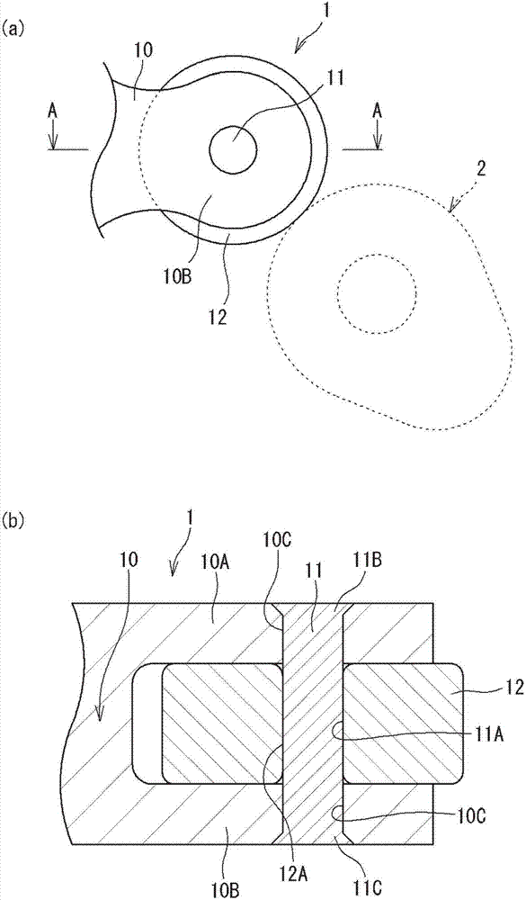
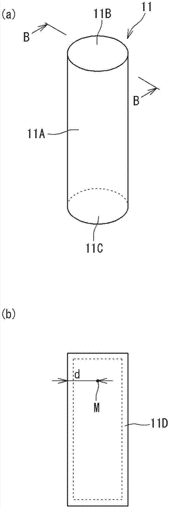
[0020] Hereinafter, a shaft member for rolling contact according to an embodiment of the present invention will be described with reference to the drawings. The rolling contact shaft member according to the embodiment of the present invention can be used as a shaft for rotatably supporting a rocker roller included in a rocker arm (rocker roller shaft). figure 1 (a) is a front view showing a part of the roller rocker using the rolling contact shaft member according to the embodiment of the present invention. figure 1 (b) is figure 1 (a) A-A line sectional view. figure 2 (a) is figure 1 A perspective view of the shaft member for rolling contact shown. figure 2 (b) is figure 2 (a) B-B line sectional view.

[0021] Such as figure 1 As shown in (a) and (b), the roller rocker arm 1 includes a rocker arm main body 10 , a rocker roller shaft (hereinafter also simply referred to as a shaft) 11 , and a rocker roller 12 in contact with the cam 2 . The rocker arm body 10 include...


PUM

PropertyMeasurementUnit
Vickers hardnessaaaaaaaaaa

Abstract

A rolling-contact shaft member, which is made of high-carbon steel and whose outer peripheral surface serves as a rolling-contact surface that rolling-contacts a mating material, includes: a carbonitrided layer having a carbon concentration of 1.1 to 1.6 wt % and a nitrogen concentration of 0.05 to 0.6 wt % in the range from the surface to the depth of 10 [mu]m. The rolling-contact shaft member has a Vickers hardness of 700 to 840 HV at the outer peripheral surface and has a Vickers hardness of 600 HV or less in its central portion. A maximum value of an absolute value of a gradient of a change in the Vickers hardness from the outer peripheral surface to the central portion is 100 to 340 HV / mm.

Description

[0001] The disclosure of Japanese Patent Application No. 2016-090736 filed on Apr. 28, 2016 including its specification, drawings and abstract is hereby incorporated by reference in its entirety. technical field [0002] The present invention relates to a shaft member for rolling contact that makes rolling contact with a counterpart member. Background technique [0003] Among the rocker arms used in valve systems of automobile engines and the like, there are roller-type rocker arms equipped with rocker rollers. In the roller-type rocker arm, a rocker roller in contact with a cam is rotatably assembled to the rocker arm via a shaft. In such a rocker arm, the inner peripheral surface of the rocker roller is in rolling contact with the outer peripheral surface of the shaft. In order to prevent damage to the shaft and prolong the rolling life of the shaft, it has been proposed to modify the steel material in the manufacturing process of the shaft. For example, Japanese Patent ...

Claims


Application Information

Patent Timeline
Patent Type & Authority Applications(China)
IPC IPC(8): F16C3/02F16C33/30F16C33/62
CPCF16C3/02F16C33/30F16C33/62F16C2223/16F16C2223/18F16C2361/31F16C2326/01F16C2202/04C23C8/80F01L1/181F01L2800/18F01L2820/01C21D1/06C21D1/18C21D1/58C21D1/63C21D9/28C23C8/32F01L2305/02F01L2301/00F01L2303/00F01L2305/00F01L1/18
Inventor 吉田亘
Owner JTEKT CORP
Features
  • R&D
  • Intellectual Property
  • Life Sciences
  • Materials
  • Tech Scout
  • Unparalleled Data Quality
  • Higher Quality Content
  • 60% Fewer Hallucinations
Learn More