Supercharge Your Innovation With Domain-Expert AI Agents!

Bearing device for wheel

一种轴承装置、车轮的技术,应用在轴承、车轴、车轮等方向,能够解决减少纤维流线截断的措施、是否能够适用或应用不清楚、相对纤维流线角度未被考虑等问题,达到滚动寿命提高、切削加工时间缩短、加工余量削减的效果

Active Publication Date: 2006-10-18
NTN CORP
View PDF1 Cites 2 Cited by
  • Summary
  • Abstract
  • Description
  • Claims
  • Application Information

AI Technical Summary

Problems solved by technology

In the above-mentioned Patent Document 1, compared with the manufacture of pipe materials, there is a description that the breakage of the fiber streamline can be reduced in the manufacture of the rod material. be considered
In addition, the manufacturing method described in Patent Document 1 is a method of manufacturing an outer ring without a flange, and it is not clear whether it is applicable or applicable to a hub ring or an outer ring with a flange.

Method used


Image

  • Bearing device for wheel
  • Bearing device for wheel
  • Bearing device for wheel

Examples


Embodiment Construction

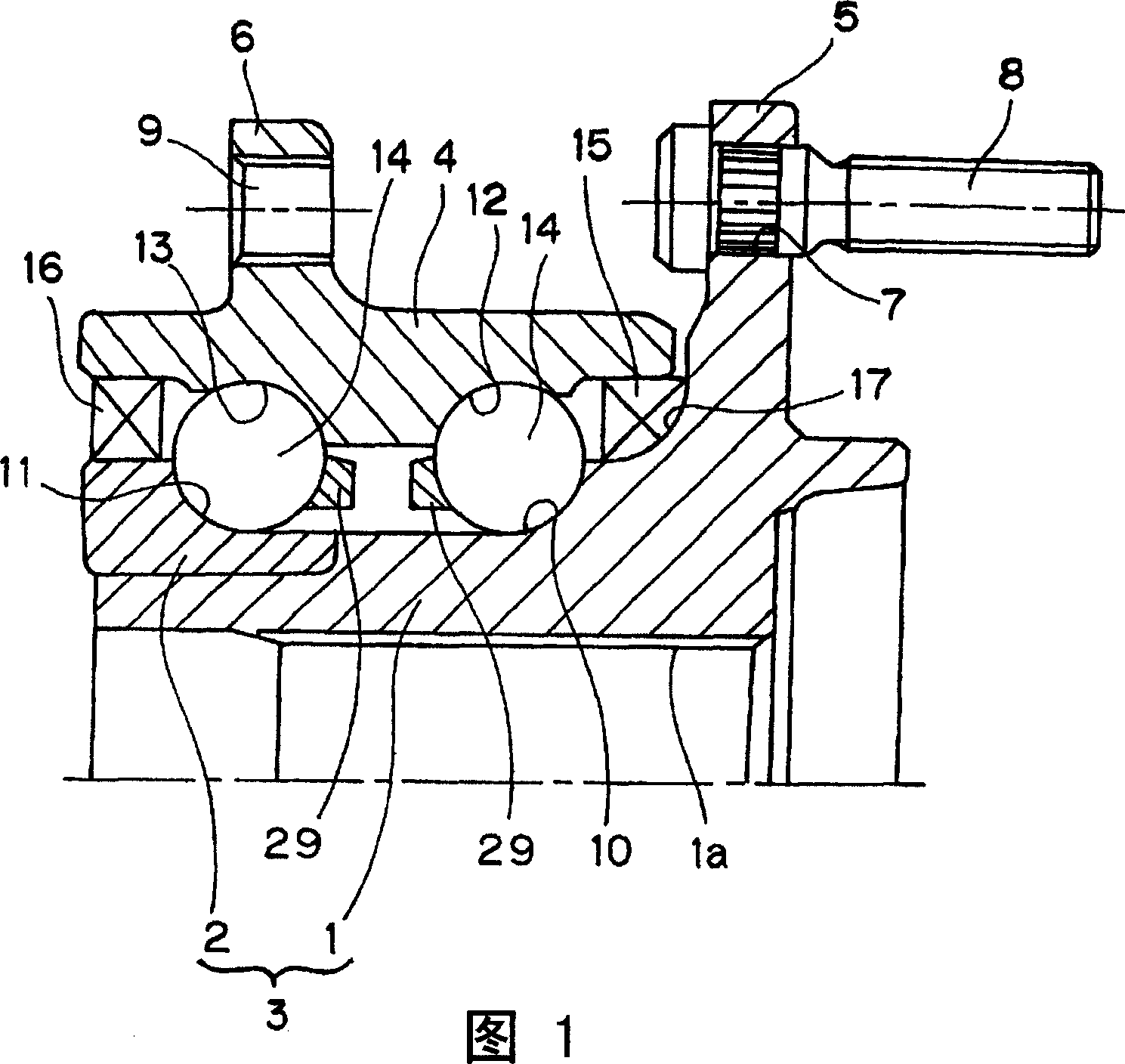
[0038] The first embodiment of the present invention will be described below based on Fig. 1 to Fig. 7 . This embodiment is an example of a third-generation spherical type, drive wheel, and inner ring rotation type wheel bearing device. The wheel bearing device includes an inner part 3 and an outer part 4. The inner part 3 is composed of a hub ring 1 and an inner ring 2 fitted with the outer circumference of the inner end of the wheel hub ring 1. The wheel bearing device is rotatable. The way to support the wheels on the vehicle body. The outer end of the hub 1 has a flange 5 for mounting a wheel, and bolts 8 for mounting a wheel are press-fitted into bolt insertion holes 7 formed at a plurality of positions in the circumferential direction of the flange 5 . In addition, this hub wheel 1 constitutes a cylindrical member through which an intermediate hole 1 a penetrates. A shaft portion of an outer joint member of a constant velocity universal joint not shown in the figure is...


PUM


Abstract

The object of the present invention is to provide a bearing device for a wheel, in which the rolling life of the raceway can be improved, and the machining allowance of the raceway can be reduced, and the weight of material input and cutting time can be shortened. A bearing device for a wheel comprises a hub ring (1) having a flange (5) for mounting a wheel and a raceway surface (10), wherein the fiber streamline (F) of the raceway surface (10) of the hub ring (1) The angle is 15° or less. In addition, the angle of the fiber streamline with respect to the track surface of the outer member not shown in the figure is also 15° or less.

Description

technical field [0001] The present invention relates to a wheel bearing device for supporting a wheel of an automobile. Background technique [0002] The hub ring and the outer ring of the bearing device for a wheel such as the hub ring assembly type are manufactured by lathe processing after forging. As a forging step, in general, for example, after cutting a carbon steel rod with a carbon content in the range of 0.4 to 0.8% along the cross-sectional direction, it is heated at around 1100°C to perform upset forging, rough forming, final forging, and ID blanking. [0003] Due to forging as above, the fiber streamlines of the rod are after forging, and the hub ring is like Figure 11 as shown, or the outer ring like Figure 13 as shown. In this figure, the finished forged shape of the hub wheel 81 or the outer ring 84 after lathe processing is indicated by a dotted line. [0004] Figure 12 said pass Figure 11 The lathe machining of the hub ring 81 forms an enlarged sec...

Claims


Application Information

Patent Timeline
Patent Type & Authority Applications(China)
IPC IPC(8): F16C33/64B60B27/00B60B35/18F16C19/16F16C19/18F16C33/60
CPCB21K1/04B21K1/40B60B27/00B60B27/0005B60B27/0094F16C19/186F16C19/187F16C33/64F16C2326/02F16C19/185
Inventor 大槻寿志高木万寿夫
Owner NTN CORP
Features
  • R&D
  • Intellectual Property
  • Life Sciences
  • Materials
  • Tech Scout
  • Unparalleled Data Quality
  • Higher Quality Content
  • 60% Fewer Hallucinations
Learn More