A laser optical lever measuring device

A measuring device, optical lever technology, applied in the direction of measuring device, using stable tension/pressure to test the strength of materials, instruments, etc., can solve the problem of unobservable changes in readings, unfavorable laboratory utilization efficiency, inconvenient operation and reading, etc. problems, to achieve the effect of improving space utilization, increasing measurement sensitivity and accuracy, and high measurement accuracy

Active Publication Date: 2019-11-01
WEIFANG UNIVERSITY
View PDF9 Cites 0 Cited by
  • Summary
  • Abstract
  • Description
  • Claims
  • Application Information

AI Technical Summary

Problems solved by technology

The magnification of the optical lever is proportional to the distance between the mirror and the scale. The greater the distance between the mirror and the scale, the greater the magnification of the optical lever and the higher the measurement accuracy. However, due to the limited space of the university laboratory, the general distance is also It is one to two meters, such a steel wire with a diameter of about 0.3mm, under the action of a Newton force, the final reading change on the scale is only about half a millimeter, and the measurement accuracy is not high
[0005] 2. It is inconvenient to operate and read. The Young’s modulus measuring instrument adjusts the tension parameters and observes the scale value at different positions. The experimenter needs to move back and forth at both ends, which affects the efficiency of the experiment, and cannot observe the process of the change of the reading when the tension changes.
[0006] 3. It is difficult to adjust the telescope, and it takes a long time to adjust the telescope so that the ruler presents a clear image in the telescope, and even the time to adjust the telescope is much longer than the specific measurement time
[0007] 4. It takes up a lot of laboratory space, which is not conducive to improving the utilization efficiency of the laboratory

Method used


Image

  • A laser optical lever measuring device
  • A laser optical lever measuring device
  • A laser optical lever measuring device

Examples


Embodiment 1

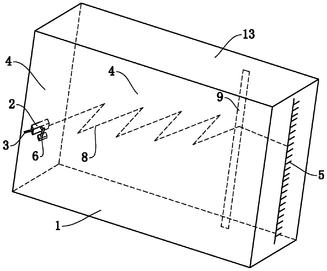
[0049] Such as Figure 1 to Figure 3 Commonly shown, a laser optical lever measuring device, including a base plate 1, a top plate 13, a laser device 2, a support foot 3, two mirrors 4 parallel to each other, a display screen 5 with a scale and a support 6, two mirrors 4 and the display screen 5 are both arranged vertically on the bottom plate 1, the top plate 13 is arranged between the tops of the two reflectors 4, and the reflective surfaces of the two reflectors 4 are oppositely arranged.

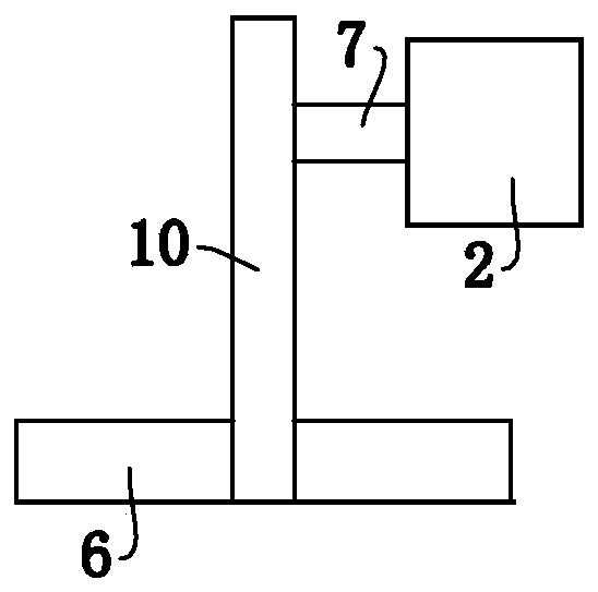
[0050] The support 6 is fixedly installed on a reflector 4, and a horizontal axis 7 is provided between the laser 2 and the support 6. One end of the laser 2 is fixedly connected to the supporting foot 3, and the other end is a laser emitting end (not shown in the figure), supporting The foot 3 and the laser emitting end are respectively located on both sides of the reflective mirror 4. The laser emitting end and the reflective surface of the reflective mirror 4 are located on the same s...

Embodiment 2

[0067] This embodiment is basically the same as Embodiment 1, the difference is that, as Figure 7 As shown, the reflective surface of the laser display position adjustment mirror 9 is a plane, and the optical path 8 between the laser display position adjustment mirror 9 and the display screen 5 is also provided with a laser inline display mirror 12, and the laser inline display mirror 12 is opposite to the laser beam. Perform horizontal widening, such as Figure 8 As shown, the laser is displayed horizontally on the display screen 5, which facilitates the reading.

[0068] Preferably, the laser inline display mirror 12 is a Powell inline lens.

Embodiment 3

[0070] This embodiment is basically the same as Embodiment 1, the difference is that, as Figure 9 As shown, the top plate 13 is provided with a guide rail 14, of course, the guide rail 14 can also be installed on the bottom plate 1, the extension direction of the guide rail 14 is consistent with the extension direction of the reflective mirror 4, and the laser display position adjustment mirror 9 is slidably installed on the guide rail 14 . In this way, the position of the laser display position adjustment mirror 9 can be changed conveniently, avoiding the problem that the laser light path deviates from the range of the laser display position adjustment mirror 9 due to changing the laser reflection angle.

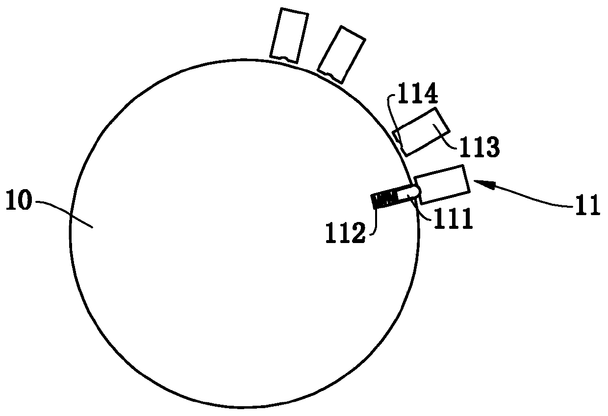
[0071] The reflective surface of the laser display position adjustment mirror 9 is a plane, the guide rail 14 is provided with a slide block 15, an angle adjustment device 16 is provided between the laser display position adjustment mirror 9 and the slide block 15, and the...


PUM


Abstract

The invention discloses a laser optical lever measurement device, which belongs to the technical field of physics experiment instruments. The device includes a bottom plate, a top plate, a laser, a support leg, two mirrors, a display with scales, and a support. The support is fixedly mounted on one of the mirrors. A horizontal shaft is arranged between the laser and the support. One end of the laser is fixedly connected with the support leg, and the other end is a laser emitting end. When the support leg moves along the vertical direction, the laser can rotate around the horizontal shaft. The angle between the projection of the light emitted by the laser on the bottom plate and the projection of the mirrors on the bottom plate is an acute angle. The laser light emitted by the laser is reflected back and forth between the two mirrors to form a light path. The display is arranged at the end of the light path. The operation and reading are convenient, and the process of change in reading along with the change in length of an object can be observed. The measuring efficiency is high. The device occupies a small space, which is conducive to improving the space utilization rate of laboratories.

Description

technical field [0001] The invention belongs to the technical field of physical experiment instruments, in particular to a laser optical lever measuring device. Background technique [0002] In various scientific experiments, it is often necessary to measure small changes in length. For example, measuring the Young's modulus of materials by stretching is one of the common ones. The traditional stretching method to measure the Young's modulus of metals uses the principle of optical levers. , the small elongation of the metal wire under the action of tension is amplified by the mirror light lever, and observed through the telescope and ruler placed in the distance. [0003] However, the above-mentioned optical lever measurement method has the following disadvantages: [0004] 1. The magnification of the optical lever is too small. The magnification of the optical lever is proportional to the distance between the mirror and the scale. The greater the distance between the mirr...

Claims


Application Information

Patent Timeline
Patent Type & Authority Patents(China)
IPC IPC(8): G01B21/06G01N3/06G01N3/08
CPCG01B21/065G01N3/068G01N3/08
Inventor 戴长志刘玉兰
Owner WEIFANG UNIVERSITY
Why Eureka
Try Eureka