Automatic ventilation system for low tier building

A ventilation system and housing technology, applied in the direction of ventilation system, roof ventilation, space heating and ventilation, etc., can solve the problems of gas flow, excessive air humidity and odor, etc., to achieve no noise, reasonable layout, no power required Effect

Inactive Publication Date: 2017-12-05
SHENYANG JIANZHU UNIVERSITY
View PDF0 Cites 4 Cited by
  • Summary
  • Abstract
  • Description
  • Claims
  • Application Information

AI Technical Summary

Problems solved by technology

[0008] The present invention aims at the above-mentioned problems, and provides an automatic ventilation system for low-rise buildings, which solves the problems that the air does not circulate when the door is closed inside the building, and there is too much moisture and peculiar smell in the air.

Method used


Image

  • Automatic ventilation system for low tier building
  • Automatic ventilation system for low tier building
  • Automatic ventilation system for low tier building

Examples


Embodiment

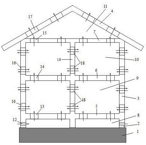
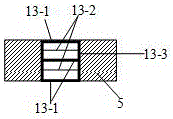
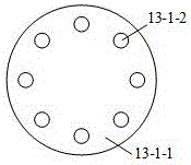
[0030] Such as Figure 1-7 As shown, the automatic ventilation system for low-rise multi-storey houses includes site foundation 1, foundation outer layer support 2, outer wall 3, roof panel 4, ground floor panel 5, middle floor panel 6, ceiling 7, foundation ventilation layer 8, and ground floor Room 9, room 10 on the top floor, attic 11, foundation one-way air inlet 12, bottom floor one-way ventilation opening 13, middle floor one-way ventilation opening 14, top floor one-way ventilation opening 15, two-way ventilation inside and outside the room against rodents, insects, and waterproof Opening 16, roof insulation and waterproof one-way air outlet 17, ventilation opening 18 between rooms and inner wall 19; foundation one-way air inlet is set at 1 / 3~2 / 3 height of foundation outer layer support 2 around foundation ventilation layer 8 Air outlet 12; several bottom floor unidirectional ventilation openings 13 are provided on the bottom floor panel 5 between the basic ventilation ...


PUM


Abstract

An automatic ventilation system for a low tier building comprises a site foundation, a ceiling, a foundation ventilation layer, bottom-layer rooms, top-layer rooms and a loft. The foundation ventilation layer is arranged on the upper portion of the site foundation, and foundation unidirectional air inlets are formed at 1 / 3-2 / 3 height of a foundation exterior support on the periphery of the foundation ventilation layer. A plurality of bottom floorslab unidirectional vents are formed on a bottom-layer floor plate between the foundation ventilation layer and the bottom-layer rooms. A plurality of middle floorslab unidirectional vents are formed on a middle floor plate between the bottom-layer rooms and the top-layer rooms. The automatic ventilation system has the advantages of reasonable layout, no need of power and zero noise. Excessive moisture and peculiar smell in air are removed while dust and pollen in air are filtered out and pure fresh air is provided to the rooms by ventilation. According to the design, fresh air is introduced to the inside of the building skillfully, and air ventilation cannot be blocked by closed doors.

Description

technical field [0001] The invention relates to an automatic ventilation system for a low-storey building, belonging to the technical fields of indoor air cleaning technology and indoor ventilation. Background technique [0002] The drivers of natural ventilation in house design are wind and temperature. The cold air is denser than the hot air, so the cold air is heavier and sinks into the depression; the hot air is lighter and rises upward. The airflow usually flows from the positive pressure area to the negative pressure area. If the airflow encounters obstacles on the way, it will cause the airflow to gather, thus forming a positive airflow area on the windward side. The wind pressure acting on the decoration design depends on the wind direction, wind speed and the decoration design shape of the clubhouse. The difference in temperature between indoor and outdoor will cause the difference in air density, resulting in a pressure difference. Therefore, for each opening, t...

Claims


Application Information

Patent Timeline
Patent Type & Authority Applications(China)
IPC IPC(8): E04B1/00E04D13/17E04B2/00E04B5/00F24F7/00F24F7/02
CPCE04B1/00E04B2/00E04B5/00E04D13/17F24F7/00F24F7/02F24F2007/004F24F2007/0025
Inventor 张延年马振宁汪青杰
Owner SHENYANG JIANZHU UNIVERSITY
Why Eureka
Try Eureka